Schottky Barrier Diode Characteristics
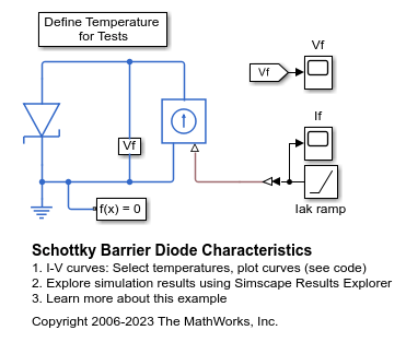
This example shows generation of the current versus voltage curve for a Schottky barrier diode. Define the vector of temperatures for which to plot the characteristics by double clicking on the block labeled 'Define Temperatures for Tests'. Run the tests and plot the I-V curves by clicking in the model on the hyperlink 'plot curves'.
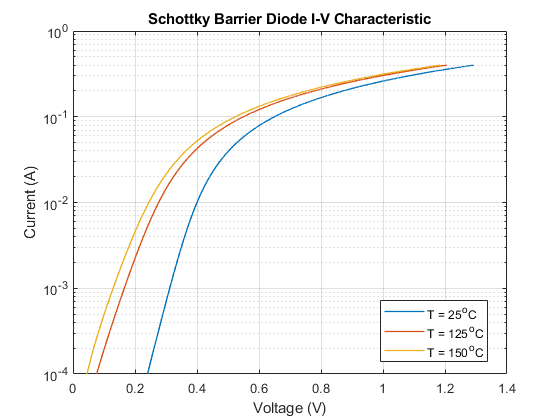
The datasheet for this device gives Vf = 0.4V when If = 10mA, and Vf = 0.65V when If = 100mA. The ohmic resistance is set to one over the gradient of the datasheet I-V curve at higher voltages. The temperature dependence is then modeled by selecting the default energy gap and saturation current temperature exponent values for a Schottky barrier diode.
The plot produced by this test model can be used to validate the implementation against the datasheet I-V plots.
Model

Simulation Results from Simscape Logging
The plot below shows the I-V characteristic for a Schottkey barrier diode extracted from simulation results. The model is simulated once for each specified temperature.

Results from Real-Time Simulation
This example has been tested on a Speedgoat Performance real-time target machine with an Intel® 3.5 GHz i7 multi-core CPU. This model can run in real time with a step size of 200 microseconds.