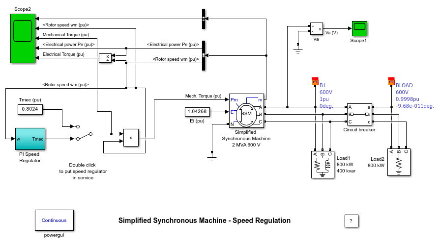
Simplified Synchronous Machine - Speed Regulation
This example shows a load shedding test on a 2000 kVA, 600 V alternator.
G. Sybille (Hydro-Quebec)

Description
A three-phase, four-wire alternator rated 2000 kVA, 1600 kW, 0.8 power factor, 600 V, 1800 rpm is connected to a 1600 kW, 400 kvar inductive load. The stator neutral point is grounded. The internal impedance of the generator (Zg = 0.0036 + j*0.16 pu) represents the armature winding resistance Ra and direct axis transient reactance X'd. The total inertia constant of the generator and prime mover is H = 0.6 s, corresponding to J = 67.5 kg.m^2. Speed regulation is modeled with Simulink® blocks implementing a PI regulator. The machine is excited with a constant voltage.
A three-phase breaker is used to switch out a 800 kW resistive load. The breaker is initially closed and it is opened at t = 0.2 s, resulting in a 50% load shedding.
Simulation
1. Initializing the machine to start in steady state
Open the Load Flow Analyzer app. The Bus type parameter of the machine is set to 'Swing Bus'. This is because the circuit contains no voltage source imposing the reference angle. The load flow is then performed with the machine controlling the voltage and the angle at its terminals. The desired terminal voltage is initialized to 600 V (machine nominal voltage) and the phase angle of UAN angle to 0 degree.
Press the 'Compute' button. Once the load flow is solved, click the 'Apply' button to initialize the machine with the solution computed by the load flow. The Analyzer prompts you with a warning to set initial condition for mechanical power to 0.8024 pu. This is because the Pm input of the machine is not connected to a constant block or to a library block (HTG or STG). Note that the mechanical torque (Tmec block) is set at 0.8024 pu. Disregard this message. Note also that the constant block Ei connected at the E input of the machine is automatically updated (E = 1.04268 pu).
2. Simulation at constant torque - No speed regulator
Make sure that the speed regulator is not in service (Manual Switch is in the upper position). Start the simulation and observe signals on Scope2. The three Iabc currents should start with steady-state sinusoidal waveforms. Observe that when the circuit breaker opens at t = 0.2 s, the electrical power (trace 4) drops from 0.8 pu to 0.4 pu and that the machine starts to accelerate.The rate of speed increase is dN/dt = 1/2H = 0.833 pu speed/ pu torque / s. As the net electromechanical torque is now Tmec-Telec = 0.8 - 0.4 = 0.4 pu, the speed increases at a rate of 0.833*0.4 = 0.33 pu/s. At t = 1.2s, the expected speed increase is therefore 0.33 pu. In fact, the speed measured at t = 1.2 s is slightly higher than the theoretical value (1.38 pu as compared to 1.33 pu). This is because the electrical torque (trace 5) decreases as speed is increasing, resulting in a net acceleration torque higher than 0.4 pu.
3. Simulation with speed regulator
Now double click on the Manual Switch block in order to put the speed regulator in service. Restart the simulation and observe the dynamic response of the speed regulator on Scope 2. Notice that in order to maintain speed at its reference value (1 pu), the speed regulator has reduced the mechanical torque to 0.4 pu.