Main Content

Solar PV System with MPPT Using Boost Converter

This example shows the design of a boost converter for controlling the power output of a solar photovoltaic (PV) system. In this example, you learn how to:

  • Determine how to arrange the panels in terms of the number of series-connected strings and the number of panels per string to achieve the required power rating.

  • Implement the maximum power point tracking (MPPT) algorithm using boost converter.

  • Operate the solar PV system in voltage control mode.

  • Select a suitable proportional gain $\left(K_v \right)$ and phase-lead time constant $\left(T_v \right)$ for the PI controller, $\frac{k_v (sT_v+1)}{sT_v }$.

The DC load is connected across the boost converter output. The solar PV system operates in both maximum power point tracking and de-rated voltage control modes. To track the maximum power point (MPP) of the solar PV, you can choose between two MPPT techniques:

  • Incremental conductance

  • Perturbation and observation

You can specify the output DC bus voltage, solar PV system operating temperature, and solar panel specification. You can use solar panel manufacturer data to determine the number of PV panels you need to deliver the specified generation capability.

Solar PV System with MPPT Using Boost Converter

To open the script that designs the Solar PV System with MPPT Using Boost Converter Example, at the MATLAB® Command Window, enter: edit 'SolarPVMPPTBoostData'

The chosen solar PV plant parameters are:

***********************************************************************************************
****                PV Plant Parameters for the Specified Solar Panel                 ****
***********************************************************************************************
*** Power rating input from the user  =  2.00 kW 
*** Minimum number of panel required per string  =  8 
*** Maximum number of panel connected per string without reaching maximum voltage  =  10 
*** Minimum power rating of the solar PV plant  =  1.80 kW 
*** Maximum power possible per string without reaching maximum DC voltage  =  2.25 kW 
*** Actual number of panel per string  =  9 
*** Number of strings connected in parallel  =  1 
*** Actual solar PV plant power  =  2.03 kW
***********************************************************************************************

Solar Plant Subsystem

The solar plant subsystem models a solar plant that contains parallel-connected strings of solar panels. A Solar Cell block from the Simscape™ Electrical™ library models the solar panel. Given the specified DC bus voltage, solar cell characteristics, and specified power rating, a calculation is made of the solar panel string length and the number of parallel-connected strings. Connecting multiple panels slows down the simulation because it increases the number of elements in a model. By assuming uniform irradiance and temperature across all the solar panels, the Solar Panel subsystem reduces the number of solar elements by using the controlled current and voltage sources.

Maximum Power Point Tracking (MPPT)

This example implements two MPPT techniques by using variant subsystems. Set the variant variable MPPT to 0 to choose the perturbation and observation MPPT method. Set the variable MPPT to 1 to choose the incremental conductance method.

Intermediate Boost DC-DC Converter

This example uses a boost DC-DC converter to control the solar PV power. The boost converter operates in both MPPT mode and voltage control mode. The model uses the voltage control mode only when the load power is less than the maximum power that the solar PV plant generates, given the incident irradiance and panel temperature.

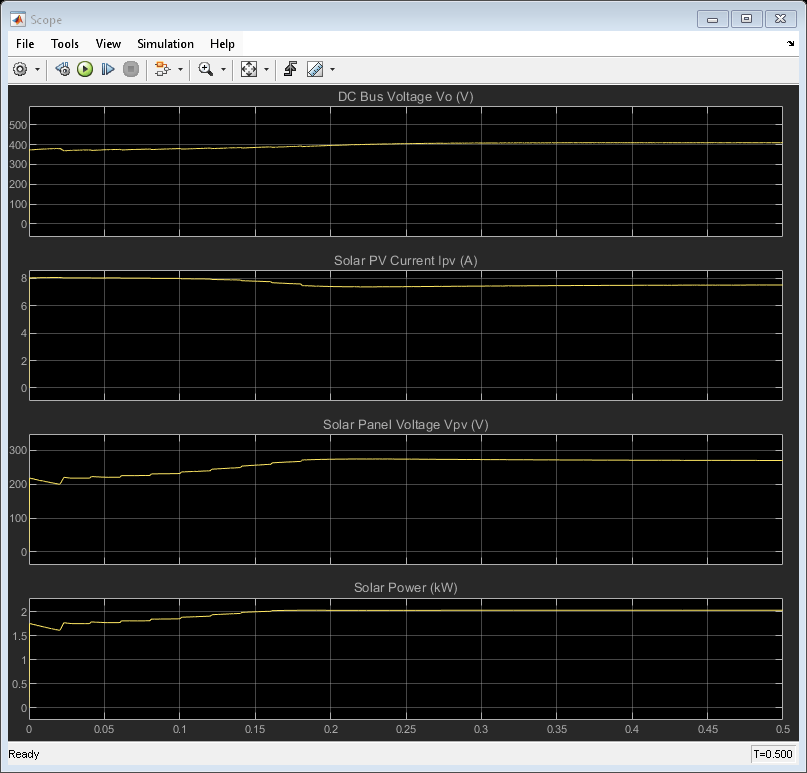
Simulation Output (MPPT Mode)