Starting a Synchronous Motor
This example shows the starting procedure for a synchronous motor.
Richard Gagnon (Hydro-Quebec)

Description
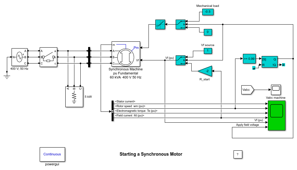
When a synchronous motor is started, the excitation DC voltage is not applied to the field winding. The motor is started in induction machine mode with currents induced in the damper and field windings. A resistor is connected across the field winding in order to produce an acceptable field current and to limit voltage induced across the field winding. Then when speed reaches a preset value near synchronous speed, the field winding is connected to the DC voltage source and the motor synchronizes on the system frequency.
In the synchronous machine model, the field winding terminals are not available. Instead, a Simulink® signal representing the field voltage must be applied at the Vf input of the machine. Therefore if the Vf input is left unconnected, a zero field voltage is applied on the rotor. In other words, the field winding is short-circuited. In this example, the field current (idf) and a gain block (R_start) are used to implement the resistance connected across the field winding.
This model illustrates the starting procedure of a 60-kVA 400-V 50Hz synchronous motor. The motor is started at no load by closing the circuit breaker at t=0.1s. A 2 pu resistor is initially connected across the field winding. When the rotor speed reaches 0.99 pu, the "R_start" resistor is disconnected from the field terminals and it is replaced by the "Vf source" (1 pu). At the same time, the mechanical power is ramped from zero to 50% of the nominal mechanical power (Pm = -0.5 pu) in one second. The motor locks into step at synchronous speed (1 pu) at approximately t = 1.3 s.
