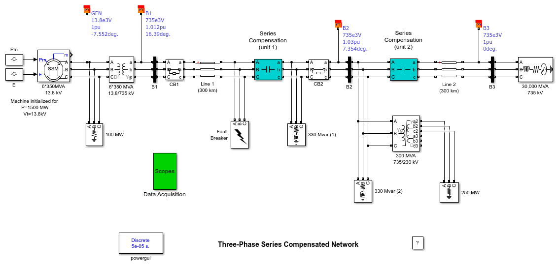
Three-Phase Series Compensated Network
This example shows the use of three-phase blocks to study transients on a series-compensated 735-kV transmission system.
G. Sybille (Hydro-Quebec)

Description
A three-phase, 60 Hz, 735 kV power system transmitting power from a power plant consisting of six 350 MVA generators to an equivalent network through a 600 km transmission line. The transmission line is split in two 300 km lines connected between buses B1,B2, and B3. In order to increase the transmission capacity, each line is series compensated by capacitors representing 40% of the line reactance. Both lines are also shunt compensated by a 330 Mvar shunt reactance. The shunt and series compensation equipment are located at the B2 substation where a 300 MVA 735/230 kV transformer with a 25 kV tertiary winding feeds a 230 kV, 250 MW load. The series compensation subsystems are identical for the two lines. For each line, each phase of the series compensation module contains the series capacitor, a metal oxide varistor (MOV) protecting the capacitor, and a parallel gap protecting the MOV. When the energy dissipated in the MOV exceeds a threshold level of 30 MJ, the gap simulated by a circuit breaker is fired. CB1 and CB2 are the two line circuit breakers.
The generators are simulated with a Simplified Synchronous Machine block. Universal transformer blocks (two-windings and three-windings) are used to model the two transformers. Saturation is implemented on the transformer connected at bus B2. Voltages and currents are measured in B1, B2, and B3 blocks. These blocks are Three-phase V-I Measurement blocks where voltage and current signals are sent to the Data Acquisition block through Goto blocks.
Fault and Line Switching
You now study the transient performance of this circuit when a line-to-ground and three-phase-to-ground faults are applied on line 1. The fault and the two line circuit breakers CB1 and CB2 are simulated with blocks from the three-phase library. Open the dialog boxes of CB1 and CB2. See how the initial breaker status and switching times are specified. A line-to-ground fault is applied on phase A at t = 1cycle. The two circuit breakers which are initially closed are then open at t = 5 cycles, simulating a fault detection and opening time of 4 cycles. The fault is eliminated at t = 6 cycles, one cycle after line opening.
Simulation
Notice that this system contains the Powergui block. In addition, when you start the system the 'SeriesCompensatedNetwork' model, the sampling time Ts = 50e-6 is automatically set in your workspace. The system is therefore discretized using a 50 microseconds sample time.
Line-to-Ground Fault
Double click the Data Acquisition block and open the three scopes. Start the simulation. As the system has already been initialized (1500 MW generation at the 13.8 kV bus) with the Load Flow utility of the Powergui, the simulation starts in steady state. At t = 1 cycle a line-to-ground fault is applied and the fault current reaches 10 kA. During the fault, the MOV conducts at every half cycle and the energy dissipated in the MOV builds up to 13 MJ.
At t = 5 cycles the line protection relays (not simulated) open breakers CB1 and CB2 and the energy stays constant at 13 MJ. As the maximum energy does not exceed the 30 MJ threshold level, the gap is not fired. After breaker opening the fault current drops to a small value and the line and series capacitance start to discharge through the fault and the shunt reactance. The fault current extinguishes at the first zero crossing after the opening order given to the fault breaker (t = 6 cycles). Then, the series capacitor stops discharging and its voltage oscillates around 220 kV.
Three-Phase-to-Ground Fault
Change the fault type to a three-phase-to-ground fault by checking Phases A, B, and C in the Fault Breaker block. Restart the simulation. Notice that during the fault the energy dissipated in the MOV builds up faster that in the case of a line-to-ground fault. The energy reaches the 30 MJ threshold level after 3 cycles, one cycle before opening of the line breakers. As a result, the gap is fired and the capacitor voltage quickly discharges to zero through the damping circuit.