Access Block State Data
To model systems that switch between periodic or continuous time dynamics, use Simulink® based states. Simulink based states are not supported in standalone Stateflow® charts in MATLAB®. For more information, see Simulink Subsystems as States.
You can read and write the state of blocks within your Simulink based states in transition actions of your Stateflow chart. You can read and write the state of blocks textually on the chart transitions or by using Simulink State Reader and State Writer blocks.
For example, the Stateflow chart in this example models a person moving through the stages of pole vaulting.
openExample("sf_pole_vault")Run_up. In the second stage, the vaulter
plants the pole and takes off, which is modeled by the Simulink based state Take_off. The final stage happens when the
vaulter clears the bar and releases the pole, which is modeled by the Simulink based state Fly.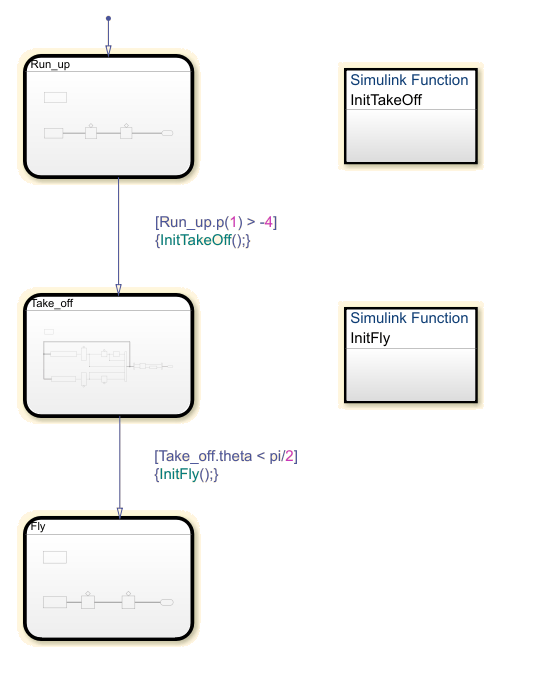
The states Run_up and Fly are easier to model by
using Cartesian coordinates. The state Take_off is easer to model by
using polar coordinates. The Simulink functions InitTakeOff and InitFly
are used to switch from one coordinate system to another. For more information on this
chart, see Model Pole Vaulter by Using Simulink Based States.
Textual Access
This subsystem is contained within the Simulink based state Run_up. For the transition
from Run_up to Take_off to occur, the
position of the pole vaulter along the x-axis, p(1), must be
greater than -4.
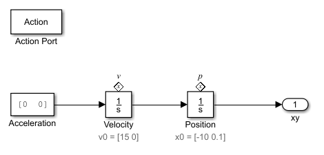
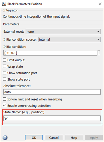
By setting the State Name of the integrator block Position to
'p', you can textually access the state of this block from
your Stateflow chart. To access the state of the integrator block in the transition
condition, type [Run_up.p(1)> -4]. When this condition becomes
true, the transition is taken and the active state becomes
Take_off.
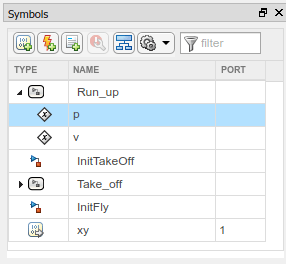
In the Symbols pane, you can see that the state
p appears under the state Run_up.
Graphical Access
Stateflow uses State Reader and State Writer
blocks to connect the subsystems within a Simulink based state to other Simulink subsystems in your model. State Reader and State
Writer blocks display the name of the state owner block that they are
connected to. Conversely, the state owner block displays a tag
![]() indicating a link to a State
Reader or a State Writer block. If you click the label
above the tag, a list opens with a link for navigating to the State
Writer block.
indicating a link to a State
Reader or a State Writer block. If you click the label
above the tag, a list opens with a link for navigating to the State
Writer block.
Connect a State Reader Block to an Owner Block
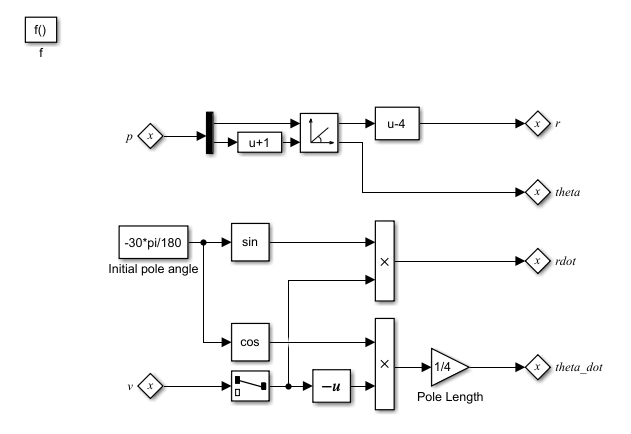
The following subsystem is contained within the Simulink function InitTakeOff. The function uses
State Reader blocks to connect to the state
Run_up and reads p and
v. The function then converts the Cartesian values for
the position of the pole vaulter and velocity into polar coordinates,
r and theta and
rdot and theta_dot, respectively.
These polar coordinates are then accessed by using state owner blocks in the
state Take_off.
When the transition action occurs, the State Reader blocks in
InitTakeOff read the state of their state owner blocks.
Once the Simulink function finishes executing, the State Writer
blocks write to the state owner blocks in the Simulink based state Take_off.
To connect a State Reader or a State Writer block to an owner block within a Simulink subsystem:
To open the properties, double-click the State Reader.
In the State Owner Selector Tree, navigate to the block that you want to be the state owner block. In this example, by choosing
Position, you connect the State Reader block to the integratorPositionin the stateRun_up.
By connecting the State Reader block to the
Positionintegrator block, this Simulink function can use the state of the integratorPositionto execute.
See Also
Topics
- Simulink Subsystems as States
- State Reader (Simulink)
- State Writer (Simulink)