使用 Stateflow 对电池管理系统进行建模
此示例对电池管理系统 (BMS) 的不同方面进行建模,并利用 Stateflow® 功能来实现系统控制。Stateflow 控制电池安全、实现故障检测、控制电池的状态并平衡电池中的电芯。
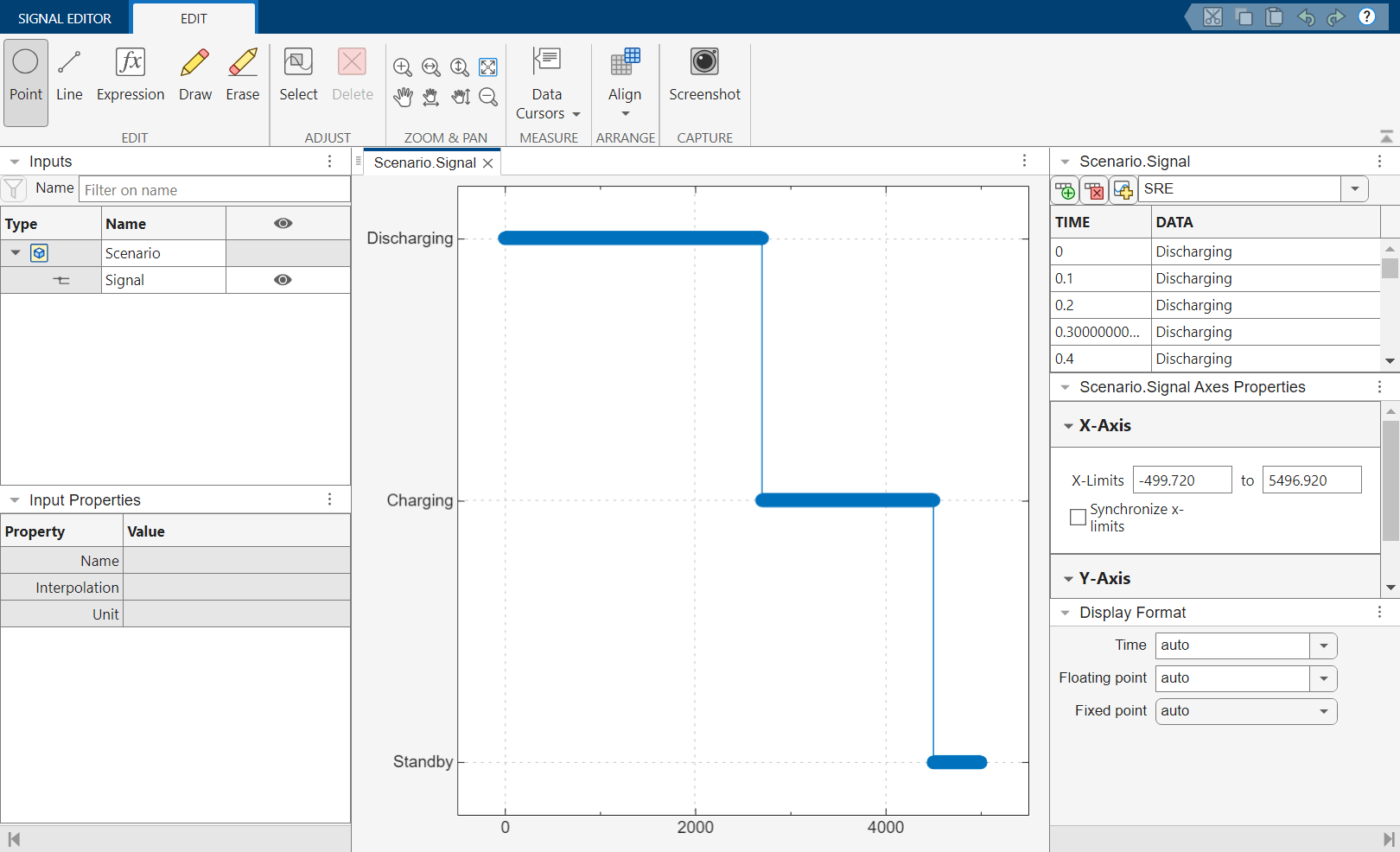
该模型包括两个主要子系统:BMS Algorithms 和 Plant Model。BMS Algorithms 子系统包含用于管理接触器和检测故障的 Power System Control 区域,以及用于确保电池安全使用和充电的 Battery Management 区域。这两个区域都严重依赖 Stateflow 才能有效运行。Plant Model 子系统对电池的物理方面(包括充电、放电和预充电电路)进行仿真以安全管理电流。Signal Editor 模块包含此系统的三种不同场景:放电、充电和待机。

管理电池安全、效率和性能
BMS Algorithms 子系统对于管理电池的安全、效率和性能至关重要。

此子系统包含两个协同工作以监控和控制电池系统各个方面的区域:Power System Control 和 Battery Management System。
电池集成
Power Control System 区域表示一个电子控制单元 (ECU),它将电池与其外部环境(例如汽车引擎)集成在一起。此区域内有两个 Stateflow 图:Contactor_Management 和 FaultDetection。
Contactor_Management 图管理接触器的断开和闭合,以确保安全操作。在此图中有两个并行状态:ChargerContactState 和 InverterContactState,它们分别控制充电和放电。

当图首次变为激活状态时,它会从两个并行故障安全状态开始:OpenChargerContacts 和 OpenInverterContacts。两个并行状态具有相似的子状态布局。当有充电或放电请求时,控制器会检查是否存在故障,然后转移为 CloseChargerContacts 或 CloseInverterContacts 状态。在闭合充电器或逆变器接触器之前,控制器会闭合预充电电路,该电路使用电容器来确保电池和负载之间的电压相等。最后,如果电压在一定时间内不相等,控制器会抛出故障。
通过使用 Stateflow 创建此控制系统,您可以确保电池安全地进入充电和放电状态。
检测电池中的故障
FaultDetection 图检测故障并对其分类,包括接触器故障、温度故障、电压故障和传感器故障。在此图中有四个并行状态:MonitorContacts、OvercurrentDetection、MonitorCellTemperature 和 MonitorCellVoltage。每个状态监控电池的一个不同方面,在每个并行状态内,都有一个链接的原子子图来监控特定故障。有些故障在触发前需要一定的成熟时间,传感器故障则将测量的电池包电压与各电芯电压之和进行比较,以确保准确检测。

例如,ContactFaultMonitoring 状态监控电池接触器中的故障。系统默认为 NoFault 状态。但是,如果检测到故障的时间长度大于 QualTime,Stateflow 会转移为两个故障状态之一:Fault1 或 Fault2。一旦进入故障状态,图会检查故障是否严重。如果故障严重,则 Critical 状态被激活,并且 Stateflow 将 CriticalFault 设置为 true。如果不严重,则 NotCritical 状态被激活。当 Stateflow 检测到故障时,并行状态 MonitorContacts 的输出变为 true。

Current Power Limits Calculation 子系统根据电芯电压和温度计算安全工作范围。该子系统还确保没有单个电芯处于过压或欠压状态,并根据最弱的电芯确定电流限值。该过程利用供应商提供的基于电压和温度的最大电流表。

管理电池运行
Battery Management System 区域表示管理电池运行状态的 ECU。此区域还包含两个 Stateflow 图:Battery Control 和 Cell Balancing。SOC Estimation 子系统估计电池的荷电状态 (SOC)。
Battery Control 图管理 BMS 的初始状态和转移。

当 Battery Control 图被激活时,它从 Normal 状态开始,并默认转移为 Standby 状态。最初,该图会检查是否存在任何严重故障。如果检测到故障,Fault 变为激活状态,BMS_State 设置为 BMS_State_Enum.BMS_Fault。如果未检测到故障,Stateflow 随后会先检查是否有放电请求,然后检查是否有充电请求。如果存在任一请求,则 Stateflow 会转移为对应的状态。
Cell Balancing 状态确保电芯之间的电压分布均匀,以保持电池健康。此状态还计算最高和最低电芯电压之间的差值,并为所需电压差生成一个命令向量。在下图中,BalancingOFF 状态首先被激活。当均衡条件全部为 true 时,图转移为 BalancingON 状态。作为默认子状态,BalActive 被激活。

当 BalancingCompleteFlag 的值变为 true 时,BalNotActive 状态被激活。BalNotActive 状态使用 exit 端口返回到 BalancingOFF 状态。
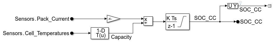
SOC Estimation 子系统使用库仑计数法估计荷电状态 (SOC),通过随时间对电流进行积分来提供电池荷电状态的准确估计。在放电期间,它随时间对电流进行积分以估计荷电状态。
对电池行为进行仿真
Plant Model 子系统对电池系统的物理方面进行仿真,从而逼真地表示电池在各种条件下的行为。
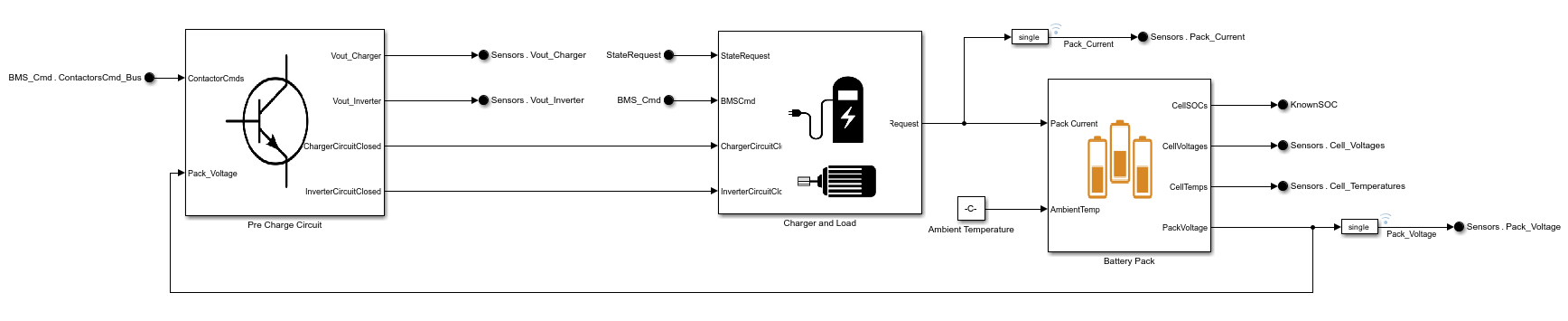
此子系统包括几个关键组件:
Charger and Load:此子系统对施加在电池上的电流需求进行仿真,无论是充电还是放电。它有助于理解电池如何响应不同充电速率和负载条件。Battery Pack:电池基于 RC 等效电路建模以估计电压和电流。它使用集总热容量模型来估计充电或放电期间的温度变化。这些模型有助于对电池的动态行为进行仿真,包括电压变化和内阻。Pre Charge Circuit:此关键的子系统可防止在将电池连接到负载或充电器时产生巨大的电流冲击。它使用大电阻逐渐均衡电压,从而确保安全连接。预充电电路包括带积分器的使能子系统,该积分器保持其值,在电路断开时对电容器充电。电阻会充电,直到其电压与电池电压匹配,此时完整电路连通,从而防止因高浪涌电流造成潜在损坏。
总的来说,Plant Model 子系统提供电池系统物理属性的动态仿真,从而能够准确测试和验证 BMS 算法,并确保安全高效的电池运行。
结果
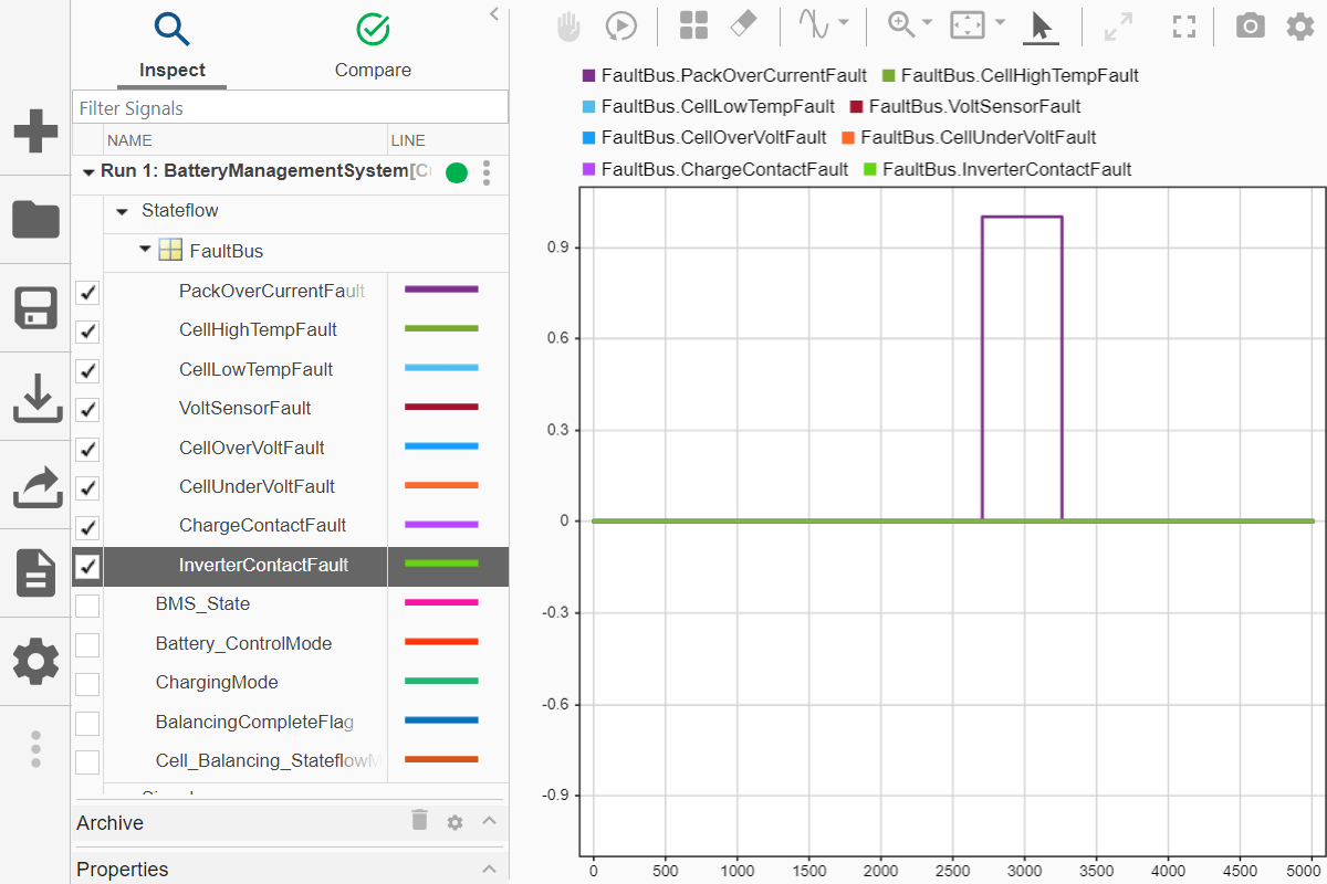
当您对此模型进行仿真时,系统会经历在 Signal Editor 模块中定义的三种不同场景:放电、充电和待机。
电池包电流、电池包电压和电芯温度都明显受到场景变化的影响。
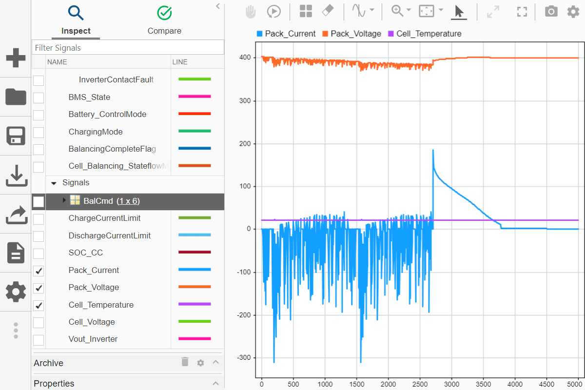
您还可以看到检测到了 PackOverCurrentFault 的位置。