Detect Common Modeling Errors During Simulation
To avoid common design errors, you can run diagnostic checks that test the completeness of your Stateflow® chart during compilation and simulation. Stateflow diagnostics detect state inconsistencies, violations in data ranges, and cyclic behavior in Stateflow charts in Simulink® models.
When you simulate a model, the Stateflow parser evaluates the graphical and nongraphical objects and data in each Stateflow machine against the supported chart notation and the action language syntax. You can also check the syntax of your chart by selecting Update Chart in the Modeling tab of the Stateflow Toolstrip.
If syntax errors exist in your chart, the chart automatically appears with the highlighted object that causes the first error. You can select the error in the diagnostic window to bring its source chart to the front with the source object highlighted. Any unresolved data or events in the chart are flagged in the Symbol Wizard.
Tip
While you edit your chart, the Stateflow Editor displays potential causes for errors by highlighting objects in red or orange. For more information, see Detect Modeling Errors During Edit Time.
Detect State Inconsistencies
In a Stateflow chart, states are inconsistent if they violate one of these rules:
An active state with exclusive (OR) decomposition and at least one substate has exactly one active substate.
All substates of an active state with parallel (AND) decomposition are active.
All substates of an inactive state are inactive regardless of the state decomposition.
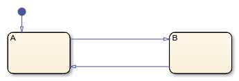
For example, this chart has a state inconsistency because there is no default transition to indicate which substate becomes active first.
Adding an unconditional default transition to one of the states resolves the state inconsistency.
At compile time, Stateflow charts detect state inconsistencies caused by the omission of an unconditional
default transition. To control the level of diagnostic action, open the Configuration
Parameters dialog box and, in the Diagnostics > Stateflow pane, set the No unconditional default transitions
parameter to error
, warning
, or
none
. The default setting is error
.
For more information, see No unconditional default transitions (Simulink).
Detect Data Range Violations
During simulation, a data range violation occurs when:
An integer or fixed-point operation overflows the numeric capacity of its result type. See Handle Integer and Enumeration Overflow for Chart Data and Fixed-Point Operations in Stateflow Charts.
The value of a data object is outside the range of the values specified by the Initial value, Minimum, and Maximum properties. See Initial value and Limit range.
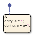
For example, this chart contains local data a
that has a
Minimum value of 0 and a Maximum value of 2. The
entry
action in state A
initializes
a
to 1. The during
action increments the value of
a
by 1. After two time steps, the value of a
exceeds
its specified range, resulting in a data range violation.
At run time, Stateflow charts detect data range violations. To control the level of diagnostic
action, open the Configuration Parameters dialog box and, in the Diagnostics > Data Validity pane, set these parameters to error
,
warning
, or none
:
Simulation range checking detects violations based on minimum-and-maximum range checks. The default setting is
none
.Wrap on overflow and Saturate on overflow detect violations that occur when integer or fixed-point operations exceed the numeric capacity of their result type. The default setting is
warning
.
For more information, see Simulation range checking (Simulink), Wrap on overflow (Simulink), and Saturate on overflow (Simulink).
Detect Cyclic Behavior
Cyclic behavior occurs when a step or sequence of steps is repeated indefinitely during chart simulation.
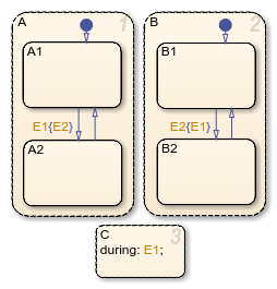
For example, the actions in this chart produce an infinite cycle of recursive event broadcasts.
The
during
action in stateC
broadcasts the eventE1
.The event
E1
triggers the transition from stateA.A1
to stateA.A2
. The condition action for this transition broadcasts the eventE2
.The event
E2
triggers the transition from stateB.B1
to stateB.B2
. The condition action for this transition broadcasts the eventE1
.
The event broadcasts in states A
and B
occur in condition actions, so the transitions do not take place until the chart processes
the resulting events. The substates A.A1
and B.B1
remain active, so new event broadcasts continue to trigger the transitions and the process
repeats indefinitely.
During chart simulation, Stateflow charts use cycle detection algorithms to detect a class of infinite recursions caused by event broadcasts. To enable cycle detection, open your Stateflow chart. In the Debug tab, select Diagnostics > Detect Cyclical Behavior. Cyclic behavior checking is selected by default.
Stateflow charts also detect undirected local event broadcasts. To control the level of
diagnostic action, open the Configuration Parameters dialog box and, in the Diagnostics > Stateflow pane, set the Undirected event broadcasts
parameter to error
, warning
, or
none
. The default setting is warning
. For more
information, see Undirected event broadcasts (Simulink).
Tip
Because undirected local event broadcasts can cause unwanted recursive behavior, use
of the send
operator to broadcast directed local events is recommended. For more information, see
Avoid Unwanted Recursion in a Chart.
Fix Cyclic Behavior in Flow Charts
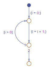
Run-time detection of cyclical behavior is limited to cases of recursion due to event broadcasts and does not extend to other types of cyclic behavior. For instance, cycle detection does not detect the infinite cycle in this flow chart. In this example, the default transition initializes the local data i
to 0. The next transition segment increments i
. The transition back to the first junction is valid when i
is positive. Because this condition is always true, an infinite cycle results.
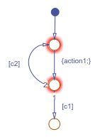
In many cases, cyclical behavior in flow charts are caused by junctions that do not have an unconditional escape path from a cycle. The Stateflow editor highlights these junctions in red. For example, in this flow chart, the top two junctions in the loop do not have an unconditional path to a terminal junction.
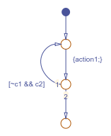
To resolve this issue, incorporate the negation of condition c1
into the transition containing c2
, so the resulting diagram has an unconditional path out of the loop.
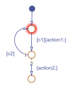
Similarly, the top junction in this flow chart does not have an unconditional path to a terminal junction.
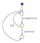
To resolve this issue, create an unconditional transition from the top junction to the terminal junction.