Implement PackML in an Automated Packaging System
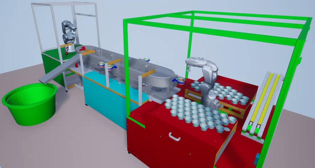
This example shows how to design Stateflow® charts that comply with the PackML standard. The example models an industrial packaging system that uses two independently operating robots arms to place balls into cups, and four shuttles to move goods along a conveyor belt. For a model that uses 3D animation to display the packaging system, see Implement Distributed Control Logic in a Flexible Manufacturing System.
The model has these features:
A human-machine interface (HMI) that allows users to monitor and operate the packaging system.
Fault management and recovery.
PLC code generation.
Examine the Automated Packaging System Model
Open the sfManufacturingSystem_PackML model.
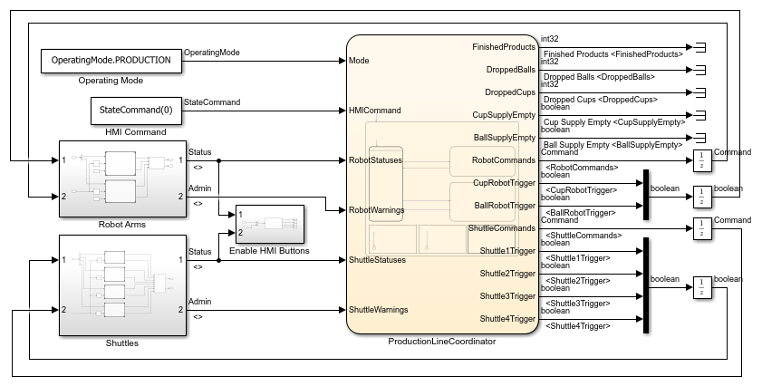
The top level of the model has these main components:
The subsystems
Robot ArmsandShuttlescontain the control logic for their respective packaging system components.The chart
ProductionLineCoordinatorcoordinates the movements of the packaging system components.
Examine PackML Interface States
To observe how the model uses PackML, from the top-level model, open the Robot Arms > Cup Robot subsystems, then open the PackML Interface chart. All robot and shuttle subsystems contain the PackML Interface chart.
In the model, the robots and shuttles operate in response to commands that come from two sources:
Internal commands that originate from the controller and concern information that the robot or shuttle can access. For example, if a robot drops an item, or a shuttle reaches a target station, the controller issues a command.
External commands that originate from the
ProductionLineCoordinatorchart. These commands include inputs from the HMI, and commands that require information not accessible to the robot or shuttle. For example, if the next station for a shuttle opens because a different shuttle leaves, theProductionLineCoordinatorchart issues a command.
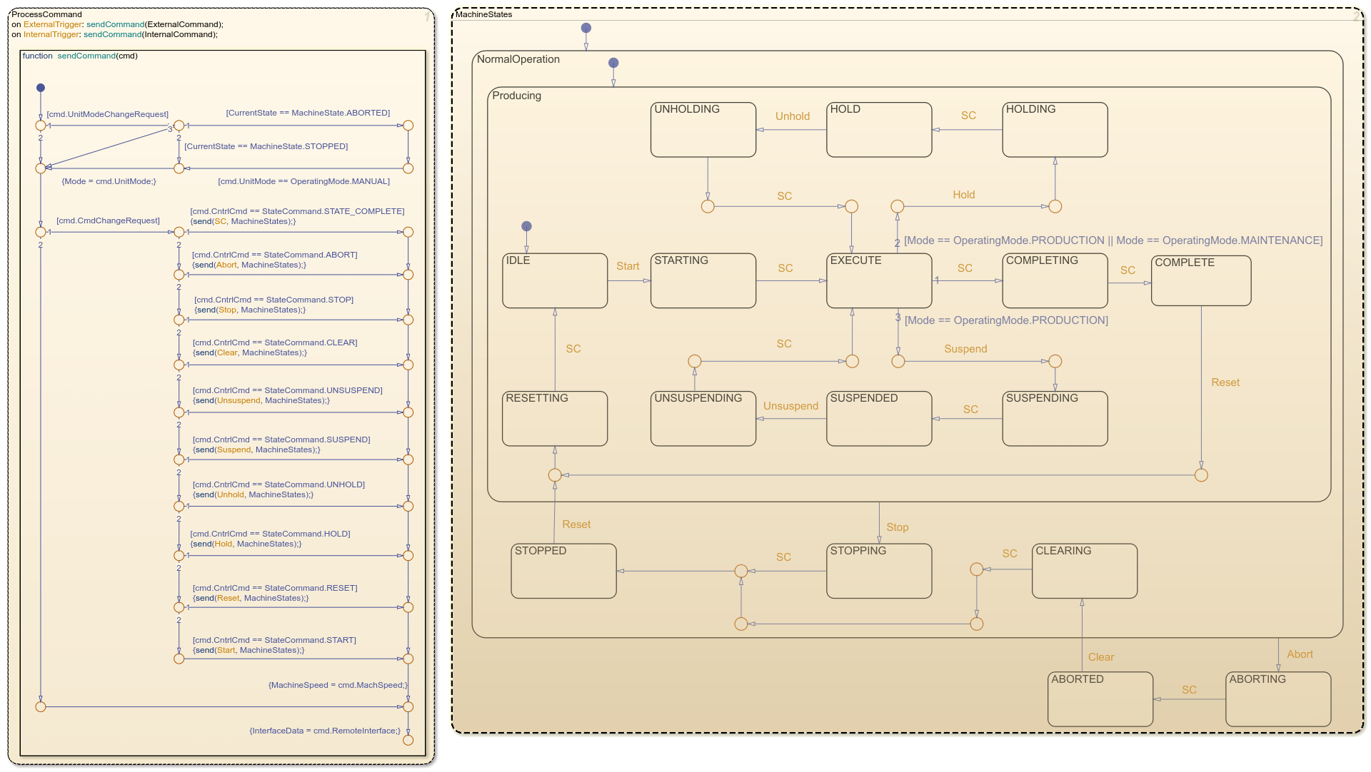
The PackML Interface chart activates when it receives an event signal for an internal or external command. Otherwise, the chart is inactive.
In the chart, the ProcessCommand state determines whether the robot or shuttle acts on a command. For example, if the command instructs the robot or shuttle to change from MANUAL operation to PRODUCTION operation, the robot or shuttle must stop first. Likewise, if the command instructs the robot or shuttle to transition to the IDLE state, but the IDLE state is already active, the robot or shuttle ignores the command.
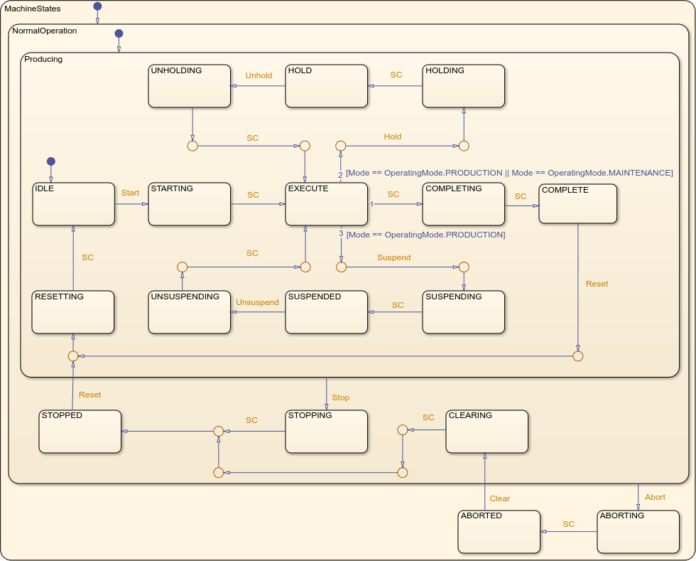
The MachineStates subchart tracks which operating mode from the PackML standard is active. The transitions in the subchart are guarded by events. When the chart receives the appropriate event from ProcessCommand, it moves along the transition.
The PackML Interface chart uses active state data to output the active state of MachineStates to other blocks in the Cup Robot subsystem. For more information, see Monitor State Activity Through Active State Data.
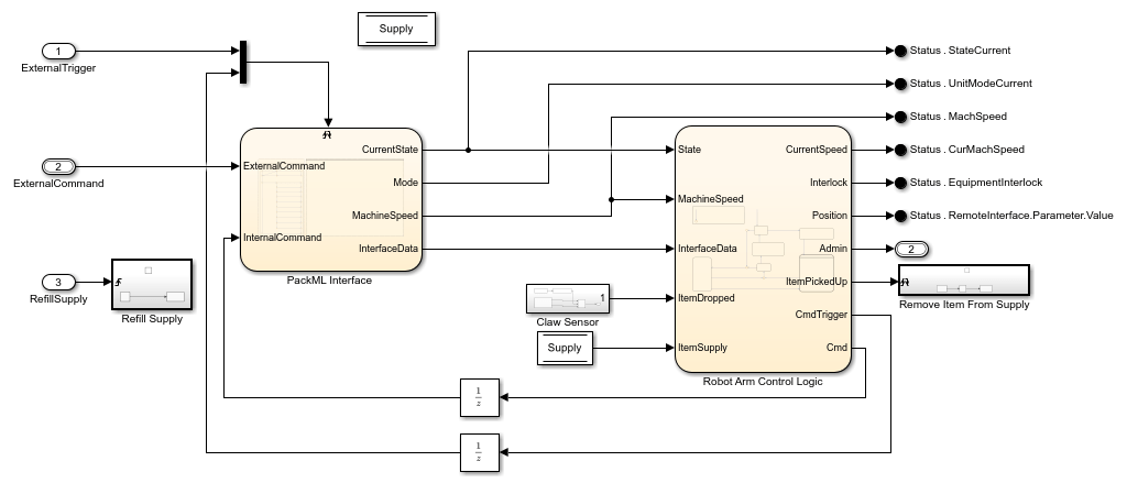
Examine the Robot Arm Control Logic Subsystem
In the Cup Robot subsystem, the Robot Arm Control Logic chart determines how the robot operates by using:
The active state of the
MachineStatesubchart.The output from the
Claw Sensorsubsystem.
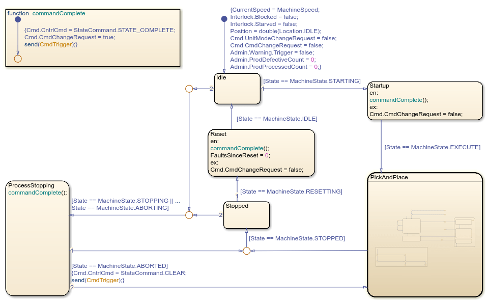
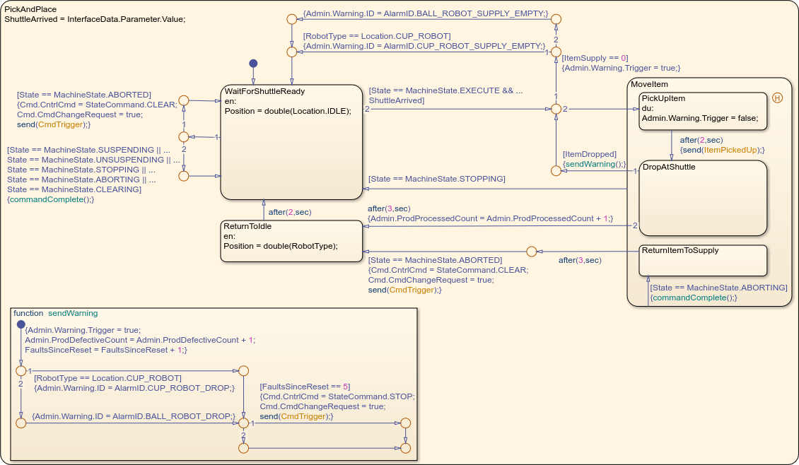
The states at the top level of the chart represent the operating modes of the robot, such as stopping or starting up. The PickAndPlace subchart contains states that represent the movements of an active robot, such as picking up or placing a ball.
Like the Robot Arms subsystem, the PackML Interface chart determines the state according to the PackML standard, while the ShuttleControlLogic chart uses the state to determine actions for the shuttle.
The robot and shuttle subsystems output the current active PackML state and other data to the ProductionLineCoordinator chart through the Status PackTag signal.
Examine the ProductionLineCoordinator Chart
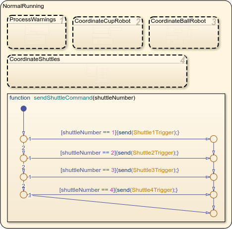
In the top-level model, the ProductionLineCoordinator chart synchronizes the operation of the robots and shuttles. For example, when a user presses a button in the dashboard to change the operating mode, the ProductionLineCoordinator chart sends the appropriate signal to every robot and shuttle.
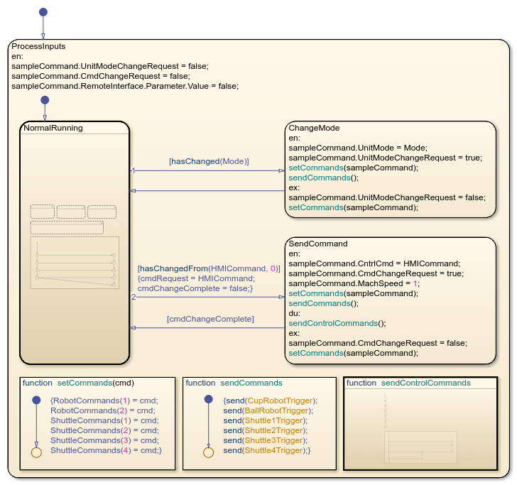
During normal operation, the chart uses the NormalRunning subchart to coordinate external commands. For example, in NormalRunning, the CoordinateCupRobot subchart prevents the cup robot from placing a cup until a shuttle is present.
Examine Fault Management
The model simulates common faults in the manufacturing process, such as dropped items or an empty supply.
If a shuttle drops a cup, the shuttle enters the
HOLDPackML state. The shuttle increases its speed until it reaches the start of the production line. Then, the shuttle leaves theHOLDstate. The ball robot does not attempt to place balls in shuttles with an activeHOLDstate.If a robot arm drops an item, it attempts to pick up another item. The shuttle waits until the robot arm is successful.
If the cup or ball supply for a robot becomes empty, the robot arm pauses operation until the supply refills.
If a shuttle or robot drops 5 items, it pauses until it receives a reset signal.
The robot and shuttle subsystems send fault and supply data to the ProductionLineCoordinator chart through the Admin PackTag signal.
Operate the Human-Machine Interface
To operate the automated packaging system, use the HMI, represented as a digital dashboard. The HMI appears when you open the model.
In the Simulation tab, click Run to simulate the model. Then, in the digital dashboard, press the Start button to begin production.
The production line starts, stops, refills, and changes operating modes in response to user input. The dials on the right side of the dashboard indicate where each shuttle is in the manufacturing system. The dashboard also displays the number of completed products, dropped items, and other production information.
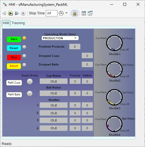
To control the production line, use the Start, Reset, Stop, and Abort buttons. If the action is invalid, the indicator light to the right of the button is gray. Otherwise, the indicator light is amber. The buttons perform these actions:
Start: Starts the production line.
Reset: Re-initializes all robots and shuttles. If the production line stops or aborts, or if a robot or shuttle drops 5 items, you must reset the production line before starting again.
Stop: All shuttles stop at the nearest station.
Abort: All shuttles speed up and return to the starting station.
To refill an empty supply for the ball or cup robot, use the Refill Cups or Refill Balls button.
To change the operating mode, at the top of the dashboard, use the Operating Mode: Value drop-down. The operating modes change how the production line reacts to faults:
In
Production, the production line responds to faults normally.In
Maintenance, production line components do not change behavior when other components experience faults. For example, if an empty shuttle moves to the ball robot station, the robot does not pause operation.In
Manual, the production line does not react to faults. For example, if a shuttle drops a cup, the shuttle does not enter theHOLDINGPackML state.
Select Components for PLC Code Generation
You can generate PLC code for these model components:
In the top-level model, the
Production Line Coordinatorchart.In the
Robot Armssubsystem, in theCup RobotandBall Robotmodel references, theRobot Arm Control Logicchart.In the
Shuttlessubsystem, in the four shuttle model references, theShuttleControlLogicchart.
For information about PLC code generation, see Generate and Examine Structured Text Code (Simulink PLC Coder).