Main Content

Create Flow Charts in Stateflow

A Stateflow® flow chart is a graphical construct that models logic patterns such as decision trees and iterative loops. Flow charts represent combinatorial logic in which one result does not depend on prior results. You build flow charts by combining only connective junctions and transitions. The junctions provide decision branches between different transition paths. Executing a flow chart begins at a default transition and ends at a terminating junction, which is a junction that has no outgoing transitions. For more information, see Combine Transitions and Junctions to Create Branching Paths.

Note

If a Stateflow chart contains only a flow chart, the chart evaluates the flow chart each time the chart wakes up. In contrast, the chart evaluates any flow chart inside a state only during state entry.

A best practice is to encapsulate flow charts in graphical functions to create modular and reusable logic that you can call anywhere in a chart. For more information about graphical functions, see Reuse Logic Patterns by Defining Graphical Functions.

For example, this flow chart models simple if-else logic:

Flow chart that models an if else statement.

The flow chart models this code:

if u > 0
   y = 1;
else
   y = 0;
end

Draw a Flow Chart

You can draw flow charts by using connective junctions as branch points between alternate transition paths. To draw a flow chart:

  1. Open a new chart.

  2. Add a default transition to the junction where the flow chart execution starts. In the object palette, click the Default transition icon . Then, on the chart canvas, click the location for the transition. The Stateflow Editor adds a new connective junction as the destination of the transition.

  3. To add a new transition, point to the border of a junction. Then, click and drag away from the junction. The Stateflow Editor provides graphical cues that allow you to add a junction or a state.

    • To place a junction at the end of the transition, click the circular cue.

    • To connect the transition to an existing junction, drag the pointer to the desired destination.

  4. To add a connective junction to the chart, in the object palette, click the Junction icon . Then, on the chart canvas, click the location for the new junction.

  5. Repeat the previous steps as required.

  6. Label the transitions as described in Define Actions in a Transition.

Best Practices for Creating Flow Charts

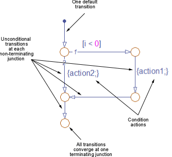
Follow these best practices when creating flow charts.

Flow chart that illustrates best practices.

Use only one default transition

Flows charts have a single entry point.

Provide only one terminating junction

Multiple terminating junctions reduce readability of a flow chart.

Converge all transition paths to the terminating junction

Execution of a flow chart always reaches the termination point.

Provide an unconditional transition from every junction except the terminating junction

If unintended backtracking occurs during simulation, a warning message appears.

To control the level of diagnostic action for unintended backtracking, open the Configuration Parameters dialog box and, in the Diagnostics > Stateflow pane, set the Unexpected backtracking parameter to none, warning, or error. The default setting is warning. For more information, see Unexpected backtracking (Simulink).

Unintended backtracking can occur at a junction under these conditions:

  • The junction does not have an unconditional transition path to a state or terminating junction.

  • Multiple transition paths lead to that junction.

To process updates, use condition actions instead of transition actions

Flow charts test transitions, but do not execute them. As a result, flow charts never execute transition actions. Furthermore, in charts that use MATLAB® as the action language, using a transition action in a graphical function results in a compile-time error.

Related Topics