Implement a PackML-Compliant Automated Packaging System
R2026bPackML (ISA-TR88.00.02-2022) defines a common set of machine states, commands, and communication structures that standardize automated packaging equipment from different vendors. This example shows how you can use Stateflow® charts to implement a PackML-compliant automated packaging system. The conveyor belt in this system has four shuttles and two robot arms that place balls into cups. The example demonstrates hierarchical state machines, event-driven transitions, state activity logging, and reusable Stateflow chart libraries.
The model includes:
Stateflow charts configured for PLC code generation
Distributed, autonomous Stateflow state machines for the robots and shuttles, and a supervisory Stateflow controller that coordinates their behavior
Fault management and recovery logic implemented in Stateflow, with simulated faults
A reusable PackML Interface chart linked from a custom block library
A human-machine interface, or HMI, implemented as a digital dashboard, that lets you monitor and operate the packaging system
For a model that uses 3-D animation to visualize the packaging system, see Implement Distributed Control Logic in a Flexible Manufacturing System.
Design Distributed and Supervisory Controllers
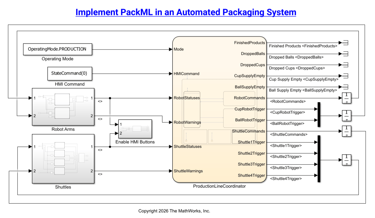
Each robot and shuttle in this system operates autonomously with its own Stateflow PackML state machine. The machines do not directly communicate with each other; instead, a supervisory Stateflow controller, the Production Line Coordinator, manages all communication between components using standardized PackTag messages. This distributed design pattern is central to the PackML architecture and uses independent state machines coordinated by a supervisory chart.
PackTags are standardized bus structures defined by PackML that all components use to communicate. A bus is a structured signal that groups multiple pieces of data together, similar to a structure in C or a record in other programming languages.
The three PackTag types used in this model are as follows:
The Admin PackTag handles production counts, defect counts, and fault reporting.
The Status PackTag handles machine states, machine speeds, equipment interlock status, and position data.
The Command PackTag handles operating modes, state commands, machine speeds, and the ready signal.
At the top level of the model, the Robot Arms and Shuttles subsystems feed Status and Admin PackTags to the Production Line Coordinator, which sends Command PackTags back. The HMI dashboard provides Operating Mode and State Command inputs to the coordinator.
Because every component uses the same PackTag structure, you can add new machine units without changing the communication protocol.
Execute Commands by Mapping PackML States to Machine Instructions
Navigate into the CupRobot Model block in the Robot Arms subsystem. Each robot and shuttle uses the same two-chart Stateflow structure.
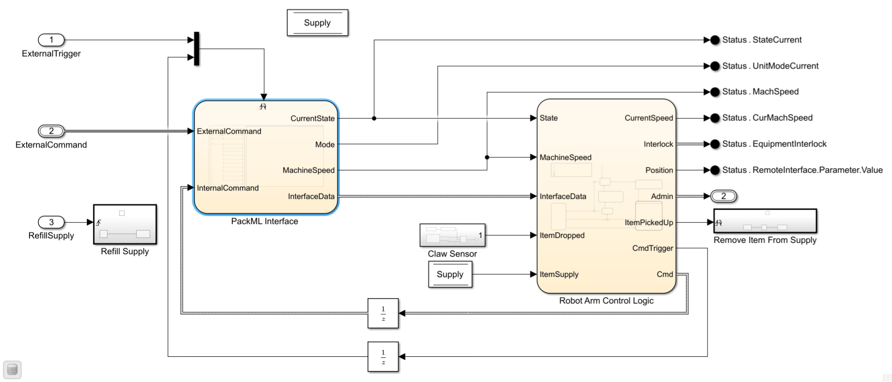
The PackML Interface chart receives Command PackTags and outputs the Status PackTag elements for the machine including PackML state, mode, machine speed, and interface data.
In turn, the Control Logic chart reads these outputs, as well as Item Supply and drop fault information, to determine what actions to perform. The Control Logic chart can also send internal commands back to the PackML interface, including STATE_COMPLETE or HOLD commands.
The Control Logic chart sends the Status and Admin PackTag information back to the supervisory controller.
Navigate to the top model, then to the Shuttles subsystem and the Shuttle1 Model. The parallel structure includes the PackML Interface and Control Logic charts. The inputs and outputs to each chart are identical. The only difference between the robots and the shuttles is what each unit does during the EXECUTE state.
The PackML Interface chart is a single Stateflow chart that implements the full PackML state machine. The PackML state machine is defined in a custom block library so that it can be instantiated for every machine unit and reused multiple times within the model.
Implement PackML in a Stateflow Chart
Open the PackML Interface chart from one of the robots or shuttles.
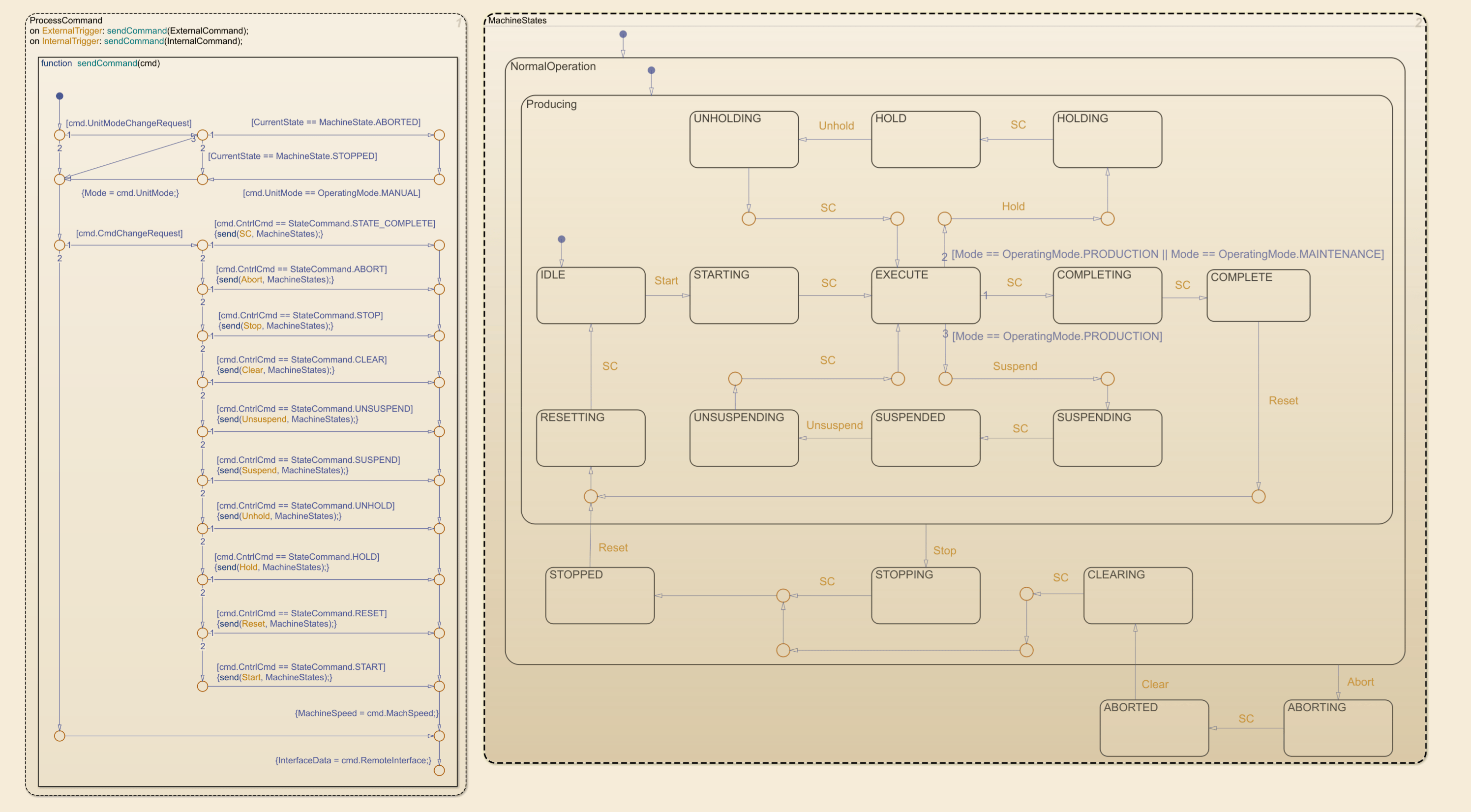
This chart demonstrates several key Stateflow features: hierarchical states that map directly to the PackML standard, event-driven communication between parallel states, transition conditions guarded by operating mode, and state activity logging for automatic state reporting.
The chart contains two parallel states, ProcessCommand and MachineStates. The dotted lines around each state indicate they are parallel, meaning they execute sequentially in the same time step. ProcessCommand processes commands and updates the current machine state first, and then MachineStates executes. The states can communicate with each other by way of events, which appear in orange font in each chart.
ProcessCommand takes incoming PackTags, both from the Production Line Coordinator and the internal control logic. When triggered, it parses the command, sets appropriate output signals, and sends a state-change event to MachineStates.
MachineStates is the PackML state machine, and its states are defined in the ISA-TR88.00.02 standard as shown below. State activity logging is enabled in the top-level state in MachineStates, so it outputs the activity of the leaf state is currently active. This configuration allows the chart to report which PackML state the machine is in without explicitly setting an output variable.
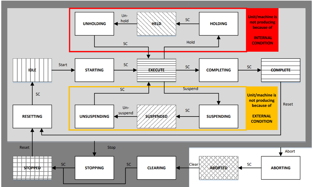
Depending on which operating mode you select, states might not be reachable. Transition conditions on each state path check the current mode, making certain states unreachable when the mode does not permit them.
In Production mode, all states are reachable.
In Maintenance mode, external faults are not registered or responded to, so SUSPEND, SUSPENDING, or UNSUSPENDING are not reachable. If a fault occurs that would incur SUSPENDING in Production mode, machines remain in EXECUTE or HOLD and the process pauses until manually reset.
In Manual mode, neither external nor internal faults are registered or responded to, so SUSPENDED, SUSPENDING, or UNSUSPENDING and HELD, HOLDING, or UNHOLDING are not reachable. All machines remain in EXECUTE and the process pauses until manually reset.
When you open the example, all machines default to the IDLE state, which can be seen by the default transition in the Producing chart within MachineStates and NormalOperation. When you press start:
The Production Line Coordinator sends a Command PackTag with
CntrlCmd = STARTto all units.ProcessCommandsends a START event toMachineStates.Machines move to STARTING, and then EXECUTE mode.
Once in EXECUTE mode, the control logic for each machine activates. For the robot arms, the activated control logic is the
PickAndPlacechart within the Control Logic chart. The shuttles have an equivalent state within their own Control Logic chart.
Coordinate Production Line Components
ProductionLineCoordinator is a Stateflow chart that serves as the supervisory controller for the system as a whole. It receives Status and Admin PackTags from all six machine units, sends Command PackTags to all units based on HMI input and system state, and monitors for faults and determines when to intervene.
Open the NormalRunning subchart within ProductionLineCoordinator. It contains four parallel subcharts that execute sequentially in the same time step:
ProcessWarningskeeps track of production counts and warnings and issues alarms.CoordinateCupRobottells the cup robot when a shuttle is waiting at its station and ready to receive a cup.CoordinateBallRobottells the ball robot when a shuttle is waiting at its station and has a cup. If a shuttle has dropped a cup, the robot suspends or skips the shuttle depending on the operating mode.CoordinateShuttlesmanages which shuttles can advance, ensures only one shuttle occupies a station at a time, and sends the Ready signal to the next shuttle when a station clears.
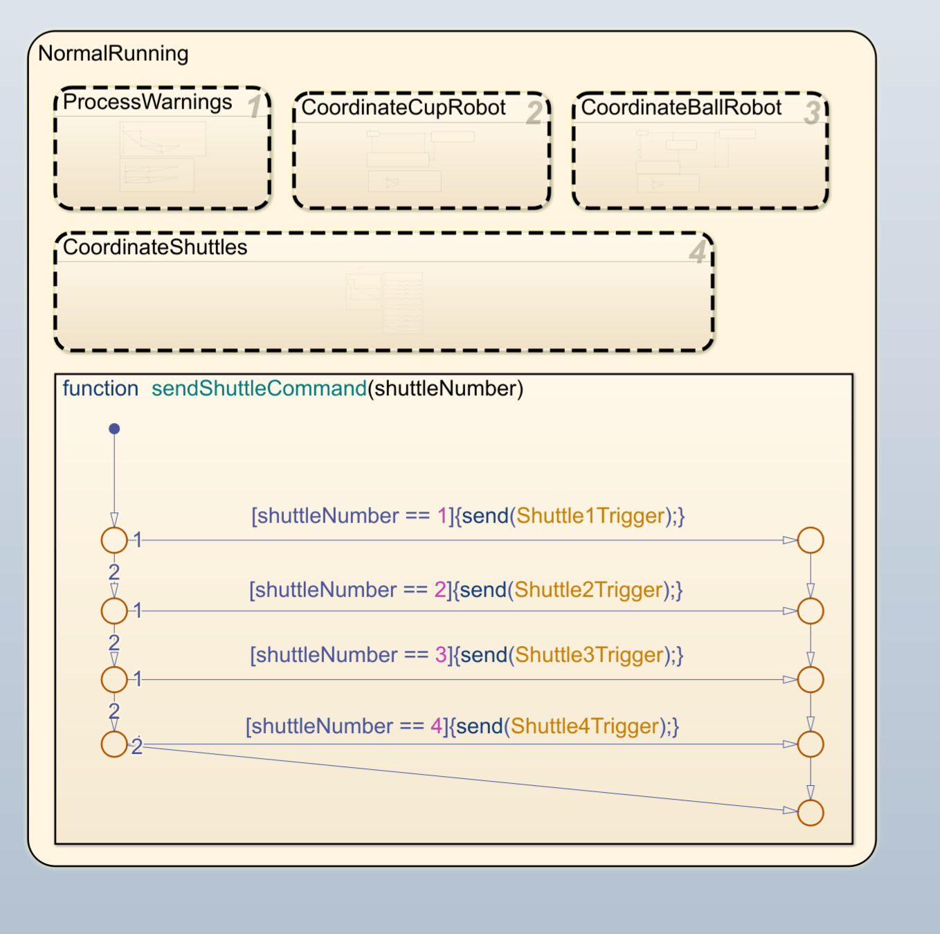
The Production Line Coordinator accomplishes all of these actions using PackTags. It reads Status.RemoteInterface.Parameter.Value to gather shuttle location information and Status.EquipmentInterlock.Starved to determine if each robot is ready to receive a shuttle. It writes Command.RemoteInterface.Parameter.Value to signal components are ready. The supervisory controller does not directly control robot arms or shuttles, but rather reads statuses and issues commands to the control logic for each chart to implement the physical action.
Model Fault Recovery Logic
Three types of fault can occur:
Dropped items: A shuttle drops a cup, or a robot drops a cup or a ball.
Admin PackTag Alarm IDs: CUP_ROBOT_DROP, BALL_ROBOT_DROP, SHUTTLE_DROP_EMPTY_CUP, SHUTTLE_DROP_FULL_CUP
Empty Supply: A cup or ball supply runs out.
Admin PackTag Alarm IDs: CUP_ROBOT_SUPPLY_EMPTY, BALL_ROBOT_SUPPLY_EMPTY
Fault Threshold: If any single component accumulates five faults, it stops itself and requires a manual reset.
FaultsSinceReset == 5
Dropped item faults for the shuttles are detected in the UpdatePosition subchart of the CircleTrack subchart within ShuttleControlLogic. If a shuttle drops a cup:
The
ControlLogicchart setsAdmin.Warning.Triggertotrue,Admin.Warning.IDto the appropriate Alarm ID, and sends aHOLDcommand to its own PackML Interface.The
ControlLogicchart also incrementsAdmin.ProdDefectiveCountandFaultsSinceReset.If
FaultsSinceReset == 5, the chart sends a STOP command to its PackML interface.
The Admin PackTag propagates to the Production Line Coordinator, which sets applicable states and fault counts in the HMI. It also suspends the ball robot if necessary.
Dropped item faults for the robots are detected in the PickAndPlace subchart of the Robot Arm Control Logic. If a robot drops a cup or a ball:
The
ControlLogicchart setsAdmin.Warning.TriggertotrueandAdmin.Warning.IDto the appropriate Alarm ID.The
ControlLogicchart also incrementsAdmin.ProdDefectiveCountandFaultsSinceReset.If
FaultsSinceReset == 5, the chart sends a STOP command to its PackML interface.
The Admin PackTag and Production Line Coordinator communicate in the same way as for the shuttles.
Empty supply faults are also detected in the PickAndPlace subchart of the Robot Arm control logic. If a cup or ball supply is empty:
The
ControlLogicchart setsAdmin.Warning.TriggertotrueandAdmin.Warning.IDto the appropriate Alarm ID.The Admin PackTag propagates to the Production Line Coordinator, which sets
CupSupplyEmptyorBallSupplyEmptytotrue.CupSupplyEmpty == trueorBallSupplyEmpty == truetriggers a red light on the HMI interface to alert the operator of empty supply.
When you press Refill Supply, the
RefillSupplysubsystem in the appropriate robot model is activated and theSupplyis refilled to 20.
These logic paths reiterate the parallel structure of the model. All faults are handled through the same Admin PackTags and involve communication between the Stateflow control logic charts and the supervisory controller.
In this example, faults are simulated using random variables representing sensor data. These triggers would come from real hardware in production, but the Stateflow PackML state machine and fault handling logic would remain identical.
Observe the Packaging System by Using the Human-Machine Interface
Open the sfManufacturingSystem_PackML model. The dashboard panel opens automatically.
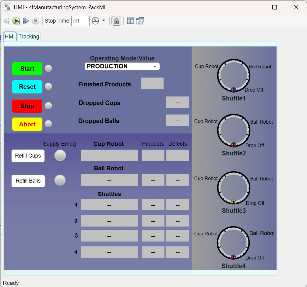
The HMI panel includes six main sections:
Command buttons: Start, Reset, Stop, and Abort
Operating Mode dropdown: Production, Maintenance, or Manual
Production Counters: Finished Products, Dropped Cups, and Dropped Balls
Supply Indicators and Refill buttons
Machine Statuses and Counters
Shuttle Position Graphic
Run the model by clicking the green Play button in the Simulink toolstrip. Then, click Start on the dashboard.
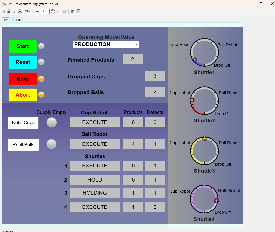
The example runs in Production mode by default. The indicators in the Shuttle Position section on the right move to show live shuttle positions as the production begins. The counters increment upwards as products are finished and cups and balls are dropped.
The cup robots and ball robots move to the EXECUTE PackML state initially and remain there during normal execution, but may enter HOLD or SUSPEND temporarily if a fault is encountered.
When the Supply Empty indicator light turns red, click Refill Cups or Refill Balls as necessary to replenish the supply and continue the simulation.
Click the Stop button on the dashboard to stop the production. Click the Stop button in the Simulink toolstrip to stop simulation.
Simulate the Model
Run the model and click Start on the dashboard. Observe the Stateflow state machines as they transition through the PackML states in real time.
The Production Line Coordinator triggers all machines to enter the EXECUTE state. The Control Logic charts then activate and begin performing the physical tasks for their respective machines. As the simulation runs, watch the machines transition from IDLE to STARTING to EXECUTE and observe how faults trigger transitions into HOLDING or HELD and SUSPENDING or SUSPENDED.
The tracking dashboard tracks shuttle motion. You can see the shuttles move incrementally from the start to the cup robot, the ball robot, the drop off, and eventually back around to the start.
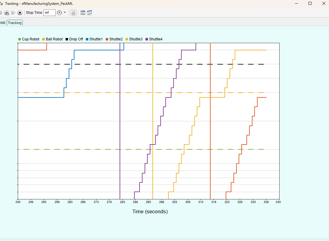
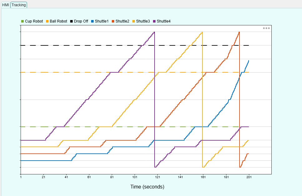
Clicking Stop stops all shuttles at the nearest station. Clicking Abort speeds up the shuttles and returns them to the nearest starting station. After being stopped or aborted, the system must be reset to return the shuttles from STOPPED to IDLE before it can be started again.
In MANUAL or MAINTENANCE mode, not all states are reachable, so the system might pause without any visible error or alert and require manual intervention when it cannot automatically handle faults through HOLD and SUSPEND.
Run the system until the supply empties. The Supply Empty fault triggers, and the light on the HMI dashboard turns red. Click Refill Cups or Refill Balls to refill the supply and continue the production.
The components in this model are defined in reusable libraries that are included in this example. The Stateflow charts here are configured for PLC code generation.

