Inspect the Design of State Transition Tables
This example shows how to verify that the sequential modal logic in a state transition table behaves as intended. State transition tables model state machines in a concise, compact format that requires minimal maintenance of graphical objects. To examine the logic of a state transition table, you can display the contents of the table as a Stateflow® chart or as a state transition matrix. You can also use highlighting to mark the primary flow of logic in your table. For more information on state transition tables, see Model Finite State Machines Using State Transition Tables.
In this example, a state transition table contains the logic for maintaining the temperature of a boiler between two set points, reference_low and reference_high. During normal operation, the boiler cycles between the states Off, Warmup, and On. For more information on this example, see Model Bang-Bang Controller by Using a State Transition Table.

Display Table as Stateflow Chart
To see a read-only Stateflow chart that shows the logic for your state transition table in a graphical format, in the Debug tab, click Show Auto Chart. Alternatively, you can convert the state transition table to a Stateflow chart by using convertToChart.

The automatically generated chart shows only the top-level states in your state transition table. To see the states and transitions at the next level of the chart hierarchy, double-click the subchart Normal.

If you modify the state transition table while the automatically generated chart is open, the chart reflects the changes that you make.
Display Table as State Transition Matrix
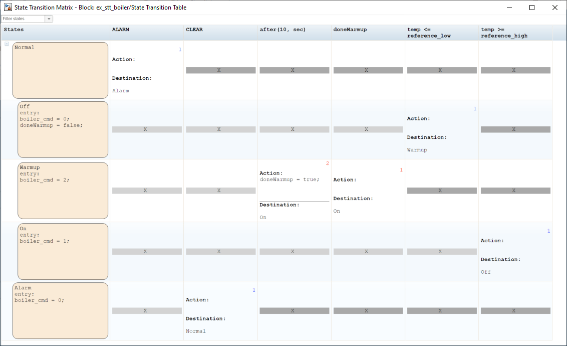
To generate a read-only state transition matrix that shows how the state transition table responds to various input conditions, in the Debug tab, click Transition Matrix.

In the state transition matrix:
Each row represents a state in the state transition table. The states appear in the same order as in the state transition table. To see only a subset of states, in the upper-left corner of the State Transition Matrix window, in the Filter states box, enter a state name or select a name from the drop-down list.
Each column corresponds to a unique condition or event in the state transition table. The order of the columns depends on the number of states that respond to each condition or event. The conditions on the left of the matrix impact more states than conditions on the right of the matrix.
Each cell lists the action and destination for a transition in the state transition table. An empty cell indicates that a condition or event does not impact a state. Empty cells to the left of a nonempty cell appear in light gray. Empty cells to the right of the last nonempty cell in a row appear in dark gray.
The execution order of each transition appears in the upper-right corner of the cell. If the transitions in a row follow the same order as the columns of the matrix, the execution order appears in blue. Otherwise, the execution order appears in red.
The state names, conditions, actions, and destinations are hyperlinks. To highlight the corresponding state, condition, action, or destination in the state transition table, click one of these hyperlinks.
If you modify the state transition table while the state transition matrix is open, the matrix does not reflect the changes that you make. To see your changes, close and regenerate the matrix.
Highlight Primary Logic Flow
To mark a sequence of transitions that represent the primary flow of logic in your state transition table, right-click each transition cell and select Mark as primary transition. For example, you can mark the transitions between the Off, Warmup, and On states that describe the normal operation of the boiler. A red border indicates the primary transition cells.

The automatically generated chart highlights the primary transitions in blue.

The highlighting persists across MATLAB® sessions. To remove the highlighting, right-click each transition cell and clear the Mark as primary transition check box.