在 Stateflow 中调度子系统
此示例说明在 Stateflow® 中调度子系统执行的三种不同方法。此模型涵盖三种不同场景:
在一个时间步中调度多个子系统
在一个时间步中多次调度一个子系统
调度多个子系统在特定时间执行
对于每种场景,您可以使用不同类型的 Stateflow 逻辑来管理子系统的执行。要在一个时间步中调度多个子系统,请使用梯形逻辑。梯形逻辑调度器设计模式允许您指定多个 Simulink® 子系统在单个时间步中的执行顺序。要在一个时间步中多次调度一个子系统,请使用循环逻辑。循环调度器设计构型允许您在一个时间步内多次执行一个 Simulink 子系统。要调度多个子系统在特定时间执行,请使用时序逻辑。时序逻辑调度器设计模式允许您调度 Simulink 子系统在指定时间执行。
在所有三个模型中,Stateflow 调度器扩展了对 Simulink 模型中子系统执行的控制,它基于模块连接和采样时间传播隐式确定执行顺序。
在一个时间步中调度多个子系统
此示例部分显示如何在 Stateflow 中设计梯形逻辑调度器。
open_system("sf_ladder_logic_scheduler")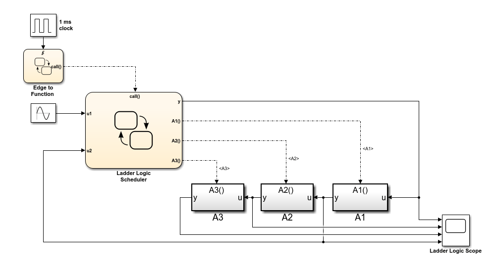
Ladder Logic Scheduler 图广播一系列函数调用输出事件,以执行三个函数调用子系统(A1、A2 和 A3)。在每个时间步中:
Simulink 模型在 1 毫秒脉冲发生器的上升沿激活
Edge to Function图。Edge to Function 图广播函数调用输出事件
call以激活Ladder Logic Scheduler图。Ladder Logic Scheduler图使用顺序梯形逻辑,根据输入信号u1和u2的值广播函数调用输出事件。

该图按顺序计算每个条件。当条件有效时,该图调用 send 运算符来广播输出事件。对应的子系统计算其输出并将控制权交还给 Ladder Logic Scheduler 图。
当您对模型进行仿真时,示波器显示每个函数调用子系统的输入和输出。在每个时间步中,Ladder Logic Scheduler 图根据输入信号 u1 和 u2 的值执行子系统:
如果
u1为正,该图会发送函数调用输出事件以执行子系统A1。此子系统将u1的值乘以增益3,并将此值作为输入u2传回 Ladder Logic Scheduler 图。控制权返回到Ladder Logic Scheduler图中的下一个条件。如果
u2大于1,该图会发送函数调用输出事件以执行子系统A2。此子系统将u2的值减少1。控制权返回到Ladder Logic Scheduler图中的最后一个条件。如果
u2小于2,该图会发送函数调用输出事件以执行子系统A3。此子系统将其输入乘以增益2。
在示波器中,水平段表示子系统未执行的时间步。
在一个时间步中多次调度一个子系统
此示例部分显示如何在 Stateflow 中设计循环调度器。
open_system("sf_loop_scheduler")
Loop Scheduler 图广播函数调用输出事件,以在每个时间步多次执行函数调用子系统 A1。在每个时间步中:
Simulink 模型在 1 毫秒脉冲发生器的上升沿激活
Edge to Function图。Edge to Function图广播函数调用输出事件call以激活Loop Scheduler图。Loop Scheduler图调用send运算符以多次广播函数调用输出事件A1。

事件 A1 的每次广播都执行子系统 A1。子系统计算其输出,并将控制权交还给 Loop Scheduler 图。
当您仿真模型时,示波器显示画面会在每个时间步显示 y 的值。在每个时间步期间,y 的值增加 25,因为:
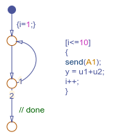
Loop Scheduler图中的流程图实现一个进行 10 次迭代的for循环。在
for循环的每次迭代中,图将y递增 1(输入u1的常量值)。每次图向子系统
A1广播输出事件时,子系统都会将y递增 1.5。
调度子系统以在特定时间执行
此示例部分显示如何在 Stateflow 中设计时序逻辑调度器。
open_system("sf_temporal_logic_scheduler")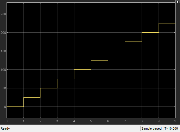
在此示例中,Temporal Logic Scheduler 图包含两个状态,它们调度三个函数调用子系统(A1、A2 和 A3)以不同速率执行,具体由时序逻辑运算符 every 确定。
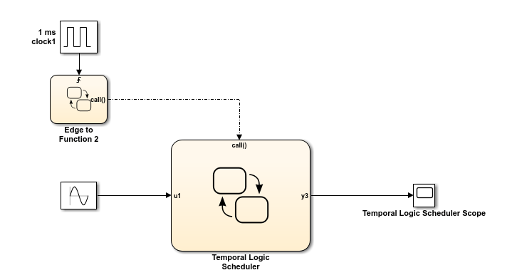
当 FastScheduler 状态被激活时,该图以输入事件 call 唤醒图的基本速率的分数倍来调度不同 Simulink 子系统的函数调用。
该图以基本速率发送事件来执行子系统
A1。该图以基本速率的一半发送事件来执行子系统
A2。该图以基本速率的四分之一发送事件来执行子系统
A3。
当 SlowScheduler 状态被激活时,该图以基本速率的 1/8、1/16 和 1/32 来调度 A1、A2 和 A3 的函数调用。
该图在 call 事件每调用 100 次后,在快速和慢速执行模式之间切换。
当您仿真模型时,示波器显示画面会在每个时间步显示 y 的值。值的变化说明执行速率的不同。
当该图以慢速执行子系统时(例如,从
t=4.5到t=4.6,从t=4.7到t=4.8,以及从t=4.9到t=5),值变化缓慢。当图以快速执行子系统时(例如,从
t=4.6到t=4.7以及从t=4.8到t=4.9),值变化迅速。
