Synchronize Actions Between Parallel States
You can make the parallel states in a Stateflow® chart run simultaneously by synchronizing the states. To synchronize parallel states, you must manually design the parallel states so that they can predictably share information with each other. For example, you can use event broadcasts to trigger parallel states to act at the same time, or use the in operator to ensure that transitions only occur based on the activity of another parallel state.
Alternatively, you can use bind function-call subsystems to control
execution based on state activity. You can also manually set state execution order for
predictable state interactions.
Broadcast Events Between Parallel States
You can use local events to synchronize the actions between parallel states. Send events
from one state by using the send action in entry,
during, exit, or transition actions to trigger
responses in other states. Configure receiving states by using on actions
or event-triggered transitions to execute when the broadcast event occurs. To qualify event
names when your chart broadcasts to specific states or substates rather than the entire
chart, use dot notation.
For example, this chart shows a temperature control system that uses event broadcasting to synchronize parallel states.
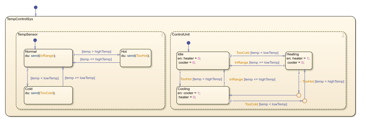
The TempSensor state monitors temperature thresholds and broadcasts
the events, TooHot, TooCold, and
InRange based on the current readings. The
ControlUnit state responds to these events and transitions between
states and activates heating or cooling equipment. This separation allows the sensor logic
to operate independently and coordinate with the control system.
Use the in Operator
To coordinate transitions between parallel states, use the in
operator to check the state activity in other parallel states. Using the
in operator in transition conditions creates dependencies between
parallel states. To evaluate if a specific substate is active, label transitions by using
in(StateName.SubstateName) syntax.
For example, this chart models a simplified a solar tracking control system. The chart
uses the in operator to synchronize transitions with the
ElevationControl state.
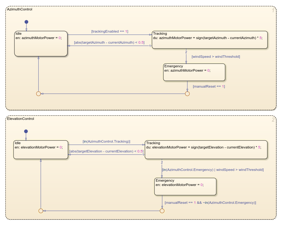
The AzimuthControl state executes first, followed by the
ElevationControl state. When executing, the
ElevationControl state checks the AzimuthControl
state to ensure that they activate in the correct sequence. Both control states can respond
to emergency conditions.
Use bind Actions with Function-Call Subsystems
A function-call subsystem is a specialized Simulink® subsystem that executes only when triggered by a function-call signal. For more information, see Using Function-Call Subsystems (Simulink).
To bind a function-call subsystem to a state, add a bind action with
the function-call event name to the state. Next, connect the event output from the chart to
the trigger port of the function-call subsystem. Set the output behavior for the disabled
subsystem to held or reset:
held: Maintains the last output values when the subsystem is disabled, which prevents output signals from suddenly changing when a state exitsreset: Returns outputs to initial values, which you can use to create clean starting conditions
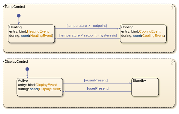
For example, in this chart, the bind actions connect states with
function-call subsystems. The model includes two parallel state machines that independently
control three subsystems through function-call events. Each subsystem activates only when
its controlling state is active. For more information, see Control Function-Call Subsystems.