Implement Adaptive Filter for Noise Cancellation Using Android Devices
This example shows how to use the Simulink® Support Package for Android® Devices to implement an adaptive filter for noise cancellation using DSP System Toolbox™.
The adaptive filter for noise cancellation system uses two input signals. The first signal being the noisy input signal, while the second input signal is uncorrelated to the desired input signal but is correlated to the noisy signal. The adaptive filter minimizes the difference between the ambient noise signal and the desired input signal by altering their filter coefficients. Over time, the output signal from the adaptive filter closely proximates the signal you want to reproduce. For more information, see Noise Cancellation in Simulink Using Normalized LMS Adaptive Filter (DSP System Toolbox).
Prerequisites
For more information on how to use the Simulink Support Package for Android Devices to run a Simulink model on your Android device, see Getting Started with Android Devices.
For more information on how to process audio signals using Android devices, complete the Get Started with Audio Signal Processing Using Android Devices and Implement Biquad and IIR Notch Filter for Noise Filtering Using Android Devices examples.
Required Hardware
Android device such as a phone or tablet
USB cable
Headphones with microphones
Hardware Setup
Connect your Android device to the host computer using the USB cable.
Connect the headphones to your Android device.
Configure Simulink Model and Calibrate Parameters
Open the androidAudioAdaptiveFiltering Simulink model.
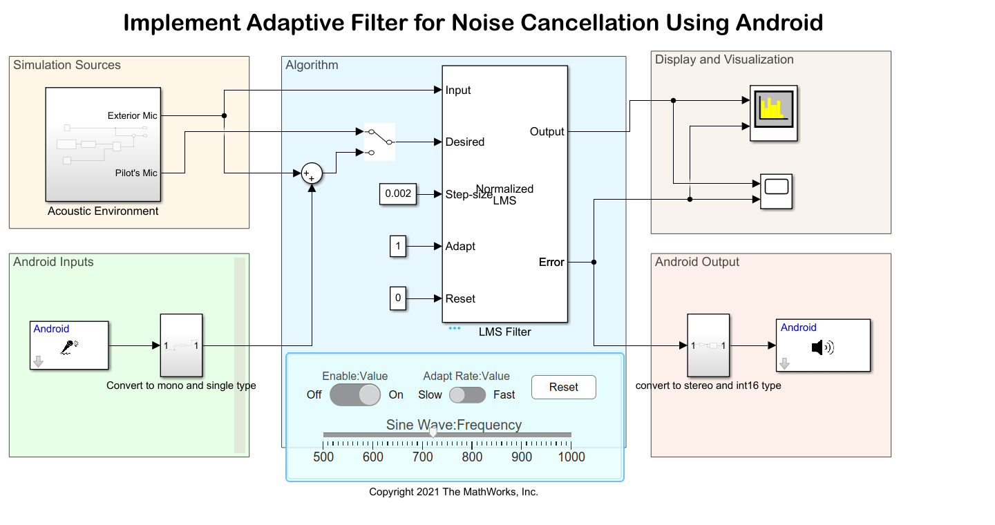
Simulation Sources
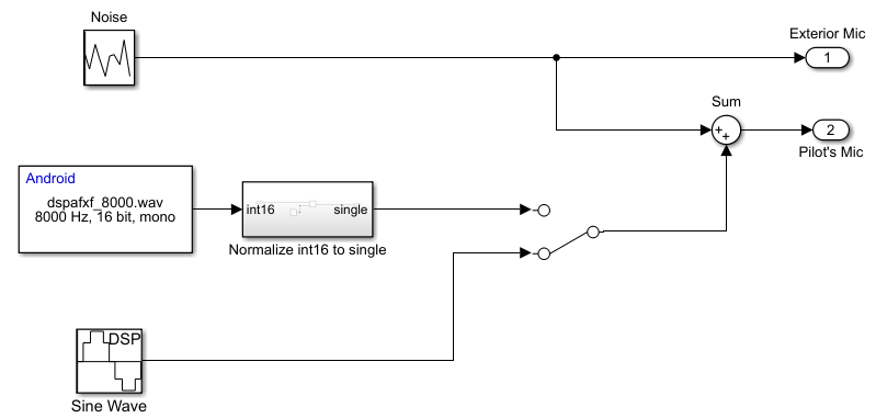
The Acoustic Environment subsystem replicates a noisy environmental scenario for simulation. In this subsystem, you can use the Random Source block to generate Gaussian white noise. To generate an audio signal, use the manual switch to select a sine wave signal or play an audio signal using the Audio File Read block. The default position of the switch is the Sine Wave block. The slider on the dashboard is connected to the frequency of the sine wave. The output from the noise source and the audio signal is summed and is input to the Desired port of the Normalized LMS block in the Algorithm area.
Android Inputs
Use the Audio Capture block to capture audio from the microphone in the deployment mode. Configure these parameters in the Block Parameters dialog box of the Audio Capture block.
Set Audio sampling frequency (Hz) to
8000.Set Frame size (N) to
800.
Algorithm
You can either enable or disable the Normalized LMS block using the Enable toggle switch on the dashboard. By default, the block is enabled.
The ambient noise and desired audio signals are two inputs to the Normalized LMS block. The Input port of the LMS Filter block receives only the noise signal input while the Desired port of the block receives a summation of the noise and the audio signal. The LMS Filter block adapts the filter weights based on the normalized LMS algorithm for filtering the input signal. Configure these parameters in the Block Parameters dialog box of the LMS Filter (DSP System Toolbox) block.
Set Algorithm to
Normalized LMS.Set Filter length to
40.Set Specify step size via to
Input port.Set Leakage factor to
1.0.Set Initial value of filter weights to
0.Select
Adapt port.Set Reset port to
Non-zero sample.Clear Output filter weights.
The step size indicates how fast the adaptive filter changes its coefficients to produce a desirable output. You can set the Step-size parameter of the LMS Filter block using the drop-down. The default value is Slow Adapt (0.002).
Press the Reset push button on the dashboard to reset the filter coefficient.
Display and Visualization
In the Display and Visualization area, you can view the Error and Output signals from the adaptive filter in the Time Scope and Spectrum Analyzer blocks.
Android Output
The output from the Error port on the Normalized LMS block is converted from single to the int16 data type in the convert to stereo and int16 type subsystem and then played on the Android speaker using the Audio Playback block.
Run Simulink Model
1. In the Simulation Sources area, open the Acoustic Environment subsystem and ensure that the manual switch receives output from the Sine Wave block.
2. On the Simulation tab of the model, click Run.
3. Open the Time Scope and Spectrum Analyzer blocks and observe the output. Initially, the signal is distorted due to the presence of noise in the desired audio signal. After some time, the noise level reduces. You can press the Reset button on the dashboard and observe how the noise levels in the audio signal reduce.

4. Now position the manual switch in the Acoustic Environment subsystem to receive output from the Audio File Read block and run the model once again. Observe the output in the time scope and spectrum analyzer.
Deploy Simulink Model on Android Device
1. In the Simulation Sources area, open the Acoustic Environment subsystem in the Simulink model and ensure that the manual switch receives output from the Sine Wave block.
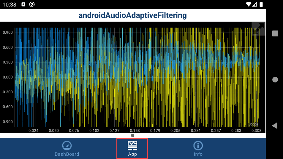
2. On the Hardware tab of the Simulink model, in the Mode section, click Run on board. In the Deploy section, click Build, Deploy & Start. The androidAudioAdaptiveFiltering application launches automatically on your Android device.
3. On the Dashboard tab of the application, change the frequency of the audio signal using the slider. Use the toggle switch to enable adaptive filtering of the audio signal and to select between slow and fast adaptive filtering rate.

4. On the App tab of the application, observe how the noise levels in the audio signal reduce.
5. Now position the manual switch in the Acoustic Environment subsystem to receive output from the Audio File Read block and redeploy the model.
6. Connect headphones to your Android device. Speak through the microphone and observe the effect of adaptive filtering.
Other Things to Try
From the dashboard, set the Adapt Rate toggle switch to Fast and observe the audio signal output in the Time Scope.
See Also
Select a Web Site
Choose a web site to get translated content where available and see local events and offers. Based on your location, we recommend that you select: United States.
You can also select a web site from the following list
Americas
- América Latina (Español)
- Canada (English)
- United States (English)
Europe
- Belgium (English)
- Denmark (English)
- Deutschland (Deutsch)
- España (Español)
- Finland (English)
- France (Français)
- Ireland (English)
- Italia (Italiano)
- Luxembourg (English)
- Netherlands (English)
- Norway (English)
- Österreich (Deutsch)
- Portugal (English)
- Sweden (English)
- Switzerland
- United Kingdom (English)