Get Started with Arduino Hardware
This example shows how to use Simulink® Support Package for Arduino® Hardware to run a Simulink model on Arduino board.
Supported Hardware:
Arduino Leonardo
Arduino Mega 2560
Arduino Mega ADK
Arduino Micro
Arduino Nano 3.0
Arduino Uno
Arduino Due
Arduino MKR1000
Arduino MKR WIFI 1010
Arduino MKR ZERO
Arduino Nano 33 IoT
Arduino Nano 33 BLE Sense
Available versions of this example:
Arduino Mega 2560 board: arduino_gettingstarted
The provided model is pre-configured for Arduino Mega 2560 and can be run on any of the board listed in the Supported Hardware section, by changing the Hardware board parameter in the Model Configuration Parameters dialog box of the model as described in Task 4 of this example.
Introduction
Simulink Support Package for Arduino Hardware enables you to create and run Simulink models on Arduino board. The target includes a library of Simulink blocks for configuring and accessing Arduino sensors, actuators and communication interfaces. Additionally, the target enables you to monitor and tune algorithms running on Arduino board from the same Simulink models from which you developed the algorithms.
In this example you will learn how to create and run a simple Simulink model on Arduino board. See other examples for Arduino board to learn how to use External mode and to learn how to implement more complex algorithms.
Prerequisites
If you are new to Simulink, we recommend completing the Interactive Simulink Tutorial, Get Started with Simulink, and Simulink Getting Started video.
Required Hardware
To run this example you will need the following hardware:
Supported Arduino board
USB cable
LED
220 Ohm resistor
Breadboard wires
Small breadboard (recommended)
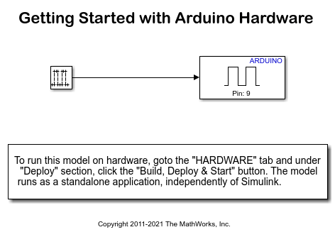
Simulink Model
Open the arduino_gettingstarted Simulink model.
Task 1 - Connect LED to Output Pin of Arduino Hardware
In this task, you will connect an LED to an Arduino output pin so you can see changes in the logical state of the pin.
1. Attach one end of the 220 Ohm resistor to output pin 9 on the Arduino board. Use the recommended breadboard and the breadboard wires.
2. Attach the long leg (positive) of the LED to the resistor. Attach the short leg (negative) to the ground pin on the Arduino board.

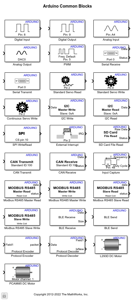
Task 2 - Review Arduino Block Library
Simulink Support Package for Arduino Hardware provides an easy way to create algorithms that use Arduino sensors and actuators by using the blocks that can be added to your Simulink model. The blocks are used to configure the associated sensors and actuators, as well as to read and write data to them.
1. Enter slLibraryBrowser at the MATLAB® prompt. This opens the Simulink Library Browser.
2. In the Simulink Library Browser, navigate to Simulink Support Package for Arduino Hardware > Common.
3. Double-click the Digital Output block. Review the block mask, which contains a description of the block and parameters for configuring the associated Arduino digital output pin.
Task 3 - Create Simulink Model for Arduino Hardware
In this task, you will create a simple Simulink model that changes the state of the Arduino digital output pin.
1. In MATLAB, select Home > New > Simulink Model.
2. Drag the Pulse Generator block from the Simulink Sources library to your model.
3. Double-click the Pulse Generator block. Set the Pulse type to parameter to Sample based and set the Sample time parameter to 0.1 second.
4. Drag the Digital Output block to the model. Use the default block settings.
5. Connect the Pulse Generator block to the Digital Output block.
Task 4 - Configure and Run the Model on Supported Arduino Hardware
In this task, you will configure and run your model on the supported Arduino board.
1. Connect the Arduino board to your computer with a USB cable.
2. In your Simulink model, click Simulation > Model Configuration Parameters to open Configuration Parameters dialog.
3. Select the Hardware Implementation pane and select your required Arduino hardware from the Hardware board parameter list. Do not change any other settings.
4. Click OK.
5. On the Hardware tab of the Simulink model, in the Mode section, select Run on board and then click Build, Deploy & Start. The Simulink model will now be deployed to the connected Arduino hardware.
6. Observe the LED connected to pin 9. The LED should blink one time every second.
7. Save your Simulink model.
A pre-configured Simulink model arduino_gettingstarted is included for your convenience.
Other Things to Try
Experiment with other blocks in the Arduino block library. For example:
Create and run a model that turns the LED on if a signal is applied to a digital input pin.
Create and run a model that repeatedly brightens and dims an LED. Hint: use the PWM block.
Select a Web Site
Choose a web site to get translated content where available and see local events and offers. Based on your location, we recommend that you select: United States.
You can also select a web site from the following list
Americas
- América Latina (Español)
- Canada (English)
- United States (English)
Europe
- Belgium (English)
- Denmark (English)
- Deutschland (Deutsch)
- España (Español)
- Finland (English)
- France (Français)
- Ireland (English)
- Italia (Italiano)
- Luxembourg (English)
- Netherlands (English)
- Norway (English)
- Österreich (Deutsch)
- Portugal (English)
- Sweden (English)
- Switzerland
- United Kingdom (English)
Asia Pacific
- Australia (English)
- India (English)
- New Zealand (English)
- 中国
- 日本Japanese (日本語)
- 한국Korean (한국어)