Getting Started with Simulink Coder Support Package for NXP FRDM-KL25Z Board
This example shows you how to use Simulink® Coder™ Support Package for NXP FRDM-KL25Z Board to run Simulink model on a NXP FRDM-KL25Z board.
Introduction
Simulink Coder Support Package for NXP FRDM-KL25Z Board enables you to create and run Simulink models on a NXP FRDM-KL25Z board. The support package includes a library of Simulink blocks for configuring and accessing NXP FRDM-KL25Z peripherals and communication interfaces.
In this example, you will learn how to configure a simple Simulink model to generate code for NXP FRDM-KL25Z board and run the generated code on the board. This model will set the on-board RGB LED to a red color.
Prerequisites
If you are new to Simulink, we recommend completing the Interactive Simulink Tutorial.
If you are new to Simulink Coder, visit the Simulink Coder product page for an overview and tutorials.
If you have not yet installed OpenSDA USB drivers, which allows your computer to recognize the FRDM-KL25Z board, follow the steps as described in the section Install Drivers for NXP FRDM-KL25Z Board.
If you have not yet updated the OpenSDA firmware and bootloader on your FRDM-KL25Z board to latest versions, follow the steps as described in the section Update OpenSDA Firmware and Bootloader for NXP FRDM-KL25Z Board.
Required Hardware
To run this example, you will need the following hardware:
NXP FRDM-KL25Z board
USB type A to Mini-B cable
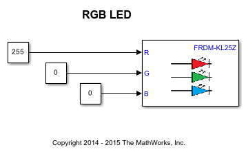
open_system('freedomboard_RGB_LED');
Task 1 - Connect an FRDM-KL25Z Board to Host Machine
In this task, you will connect FRDM-KL25Z board to host machine.
1. Plug in a Mini USB cable from a USB port on the host machine to the OpenSDA mini-B USB connector on the FRDM-KL25Z board.
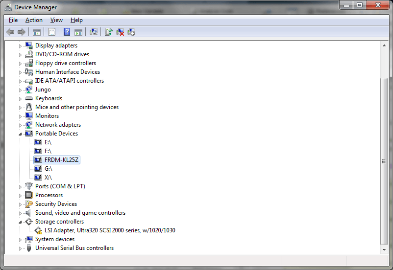
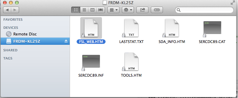
2. The FRDM-KL25Z comes with the mass-storage device (MSD) Flash Programmer OpenSDA Application preinstalled.
On Windows®, It will appear as a removable storage drive with a volume label of FRDM-KL25Z.
On Mac, It will appear as a removable storage drive with a volume label of FRDM-KL25Z.
Task 2 - Review NXP FRDM-KL25Z Support Package Block Library
1. Enter simulink at the MATLAB® prompt. This opens the Simulink Library Browser.
2. In the Simulink Library Browser, navigate to Simulink Coder Support Package for NXP FRDM-KL25Z Board > FRDM-KL25Z.
3. Double-click the RGB LED block. Review the block mask, which contains a description of the block and block inputs the associated RGB LED.
open_system('frdmkl25zlib');

Task 3 - Create a Model for NXP FRDM-KL25Z Board
In this task, you will create a simple Simulink model that sets the color of the RGB LED to red.
1. In MATLAB, select HOME > New > Simulink Model. Under Simulink, select Blank Model > Create Model.
2. Drag the Constant block from the Simulink Sources library to your model. Set the value of Constant block to 255.
3. Drag the RGB LED block from FRDM-KL25Z library to the model.
4. Connect the Constant block to the R input of RGB LED block.
5. Copy the Constant block to your model and set the value to 0. Then Connect the Constant block to the G input of RGB LED block.
6. Make one more Copy the Constant block to your model and set the value to 0. Then Connect the Constant block to the B input of RGB LED block.
Task 4 - Configure and Run the Model on NXP FRDM-KL25Z Board
In this task, you will configure and run your model on the NXP FRDM-KL25Z Board
1. Connect the NXP FRDM-KL25Z Board to your computer with a USB cable.
2. In your Simulink model, click on the Configuration Parameters button.

3. When the Configuration Parameters page opens up, navigate to Hardware Implementation pane.
Set the Hardware board parameter to NXP FRDM-KL25Z.
On the Target Hardware Resources pane, Set the Build action to Build, load and run to automatically download the generated binary file on to the connected NXP FRDM-KL25Z board.
4. Navigate to Solver pane and set the Solver to discrete (no continuous states).
5. Click OK.
6. In your Simulink model, click the Build Model button on the toolbar. The model will now be deployed to the NXP FRDM-KL25Z Board.

7. Observe that the RGB LED is set with RED color.
8. Save your model.
A pre-configured model is included for your convenience.
Other Things to Try with RGB LED Block
For example:
Create and run a model that turns the RGB LED to different colors.
Create and run a model that toggles the RGB LED to R, G, and B colors.
You can also select a web site from the following list:
Americas
- América Latina (Español)
- Canada (English)
- United States (English)
Europe
- Belgium (English)
- Denmark (English)
- Deutschland (Deutsch)
- España (Español)
- Finland (English)
- France (Français)
- Ireland (English)
- Italia (Italiano)
- Luxembourg (English)
- Netherlands (English)
- Norway (English)
- Österreich (Deutsch)
- Portugal (English)
- Sweden (English)
- Switzerland
- United Kingdom (English)