Configure Image and Device Properties of Raspberry Pi V4L2 Video Capture Block to Detect Objects
This example shows how to configure the image and device properties of the V4L2 Video Capture block from Simulink® Support Package for Raspberry Pi® Hardware and observe the output in the SDL Video Display block. This example also shows how to tune the image properties of the V4L2 Video Capture block to detect objects in a noisy and distorted real-time video.
Prerequisites
For more information on how to use Simulink Support Package for Raspberry Pi Hardware, see Get Started with Simulink Support Package for Raspberry Pi Hardware.
Required Hardware
Raspberry Pi hardware board
USB webcam compliant with universal video class (UVC) standards
Hardware Setup
Connect the webcam to your Raspberry Pi hardware board.
Task 1: Change V4L2 Video Capture Block Parameters and Observe Changes in SDL Video Display Block
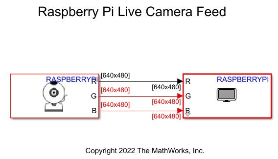
Open a new Simulink blank model and connect the V4L2 Video Capture and SDL Video Display blocks.
Connect your webcam to the Raspberry Pi board. Place some objects in front of the webcam.
On the Hardware tab of the Simulink model, in the Mode section, click Run on board and then select Connected IO from the drop-down list. In the Run on Computer section, click Run with IO. Open the SDL Video Display window.
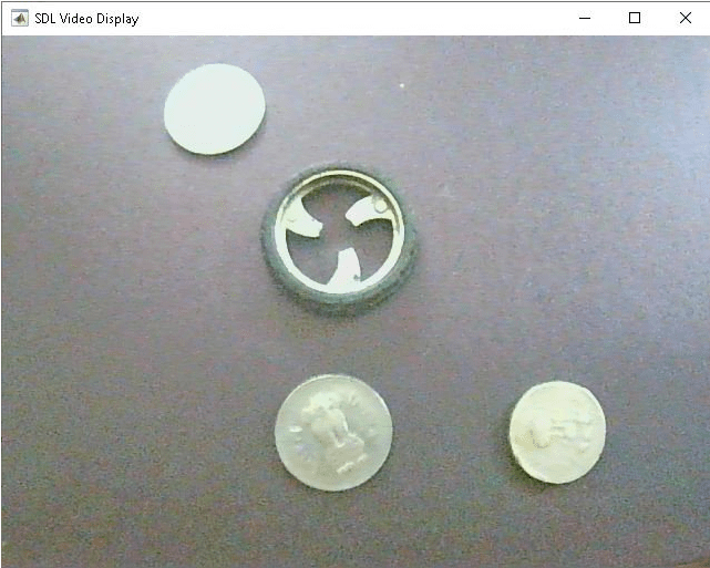
Perform these actions in the V4L2 Video Capture block and observe the effect on the image in the SDL Video Display window.
1. On the Basic tab of the V4L2 Video Capture Block Parameters dialog box:
Select Flip image along horizontal axis to rotate the image along the horizontal axis.
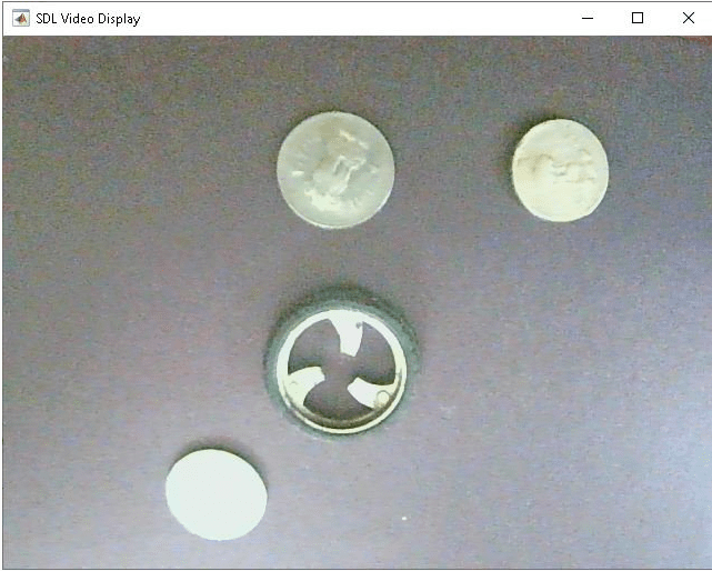
Select Flip image along vertical axis to rotate the image along the vertical axis.
2. On the Advanced tab of the V4L2 Video Capture Block Parameters dialog box:
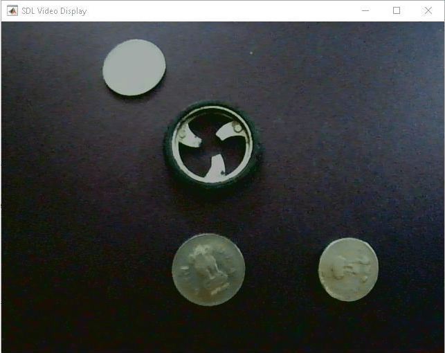
Use the sliders to change the brightness of the image.
Image with High Brightness
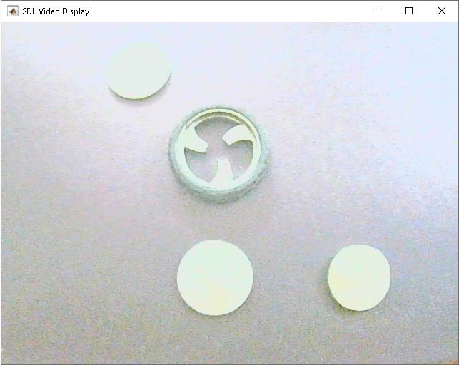
Image with Low Brightness
Adjust other image and device properties in the Advanced tab of the block and observe the output on the SDL Video Display block. For more information, see V4L2 Video Capture.
Task 2: Detect Object Using V4L2 Video Capture Block
Open the raspberrypi_object_detection Simulink model.
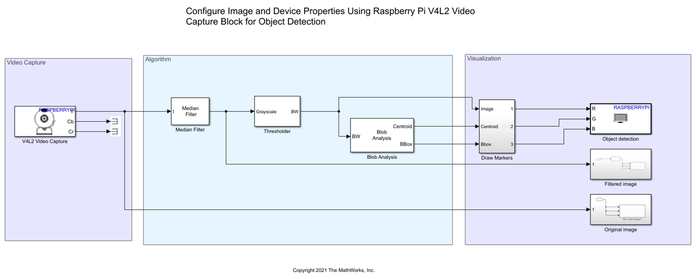
Video Capture
The V4L2 Video Capture block in the Video Capture section supports video capture from UVC-compliant USB webcams. The webcam should also support data acquisition in the YUYV (luma and luminance) mode. Connect the webcam to your Raspberry Pi board using a USB cable.
Configure these parameters in the V4L2 Video Capture Block Parameters dialog box.
Set Image size to
640x480.Set Pixel format to
YCbCr 4:2:2.Set Sample time to
1/30.
The Y output port of the V4L2 Video Capture block contains the grayscale image.
Algorithm
The Median Filter block in the Algorithm area reduces the impulsive noise present in the grayscale images that the V4L2 block captures.
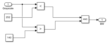
The Thresholder subsystem converts the grayscale image to binary image.
The Blob Analysis block computes statistics for the detected objects. In this example, the block computes image statistics such as centroid and bounding box.
Configure this parameter in the Main tab of the Blob Analysis Block Parameters dialog box.
Select Centroid and Bounding box.
Configure these parameters in the Blob Properties tab of the Blob Analysis Block Parameters dialog box.
Set Maximum number of blobs to
5. This parameter determines the maximum number of objects that the block detects.Select Specify minimum blob area in pixels to
1000.Select Specify maximum blob area in pixels to
100000.
Visualization
The Draw Markers subsystem in the Visualization area accepts three inputs.
Binary image from the
ThresholdsubsystemCentroid coordinates of the object detected on the binary image
Bounding box coordinates for the object detected on the binary image
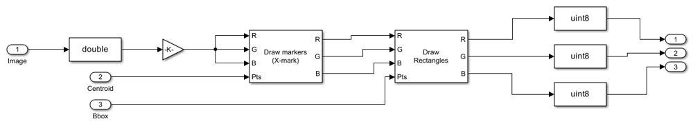
The Draw Markers block uses the centroid coordinate points of the detected object as an input to draw a marker on the centroid point. In this example, the letter X is used to indicate the centroid of the detected object.
Configure these parameters in the Draw Markers Block Parameters dialog box.
Set Marker shape to
X-mark.Set Border color to
User-specified value.Set Color value(s) to
[255 0 0].Set Image signal to
Separate color signals.
The Draw Shapes block uses the bounding box coordinate points of a detected object as an input to draw a bounding box around it. In this example, a rectangular box is used to draw a bounding box around the detected object.
Configure these parameters in the Draw Shapes Block Parameters dialog box.
Set Shape to
Rectangle.Set Border color to
User-specified value.Set Color value(s) to
[255 0 0].Set Image signal to
Separate color signals.
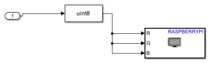
The image data is converted from data type double to uint8 segregated as individual R, G, and B data signals and given as an input to the SDL Video Display block.
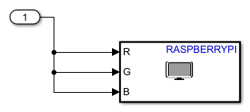
The Filtered image subsystem displays the image data after passing it through a median filter.
The Original image subsystem displays the original image data that is captured using the V4L2 Video Capture block.
Run Simulink Model in Connected IO Mode
You can make changes in the image properties of the V4L2 Video Capture dialog box and observe them simultaneously in the SDL Video Display window. For more information, see Communicate with Hardware Using Connected IO.
On the Hardware tab of the Simulink model, in the Mode section, click Run on board and then select Connected IO from the drop-down list. In the Run on Computer section, click Run with IO.
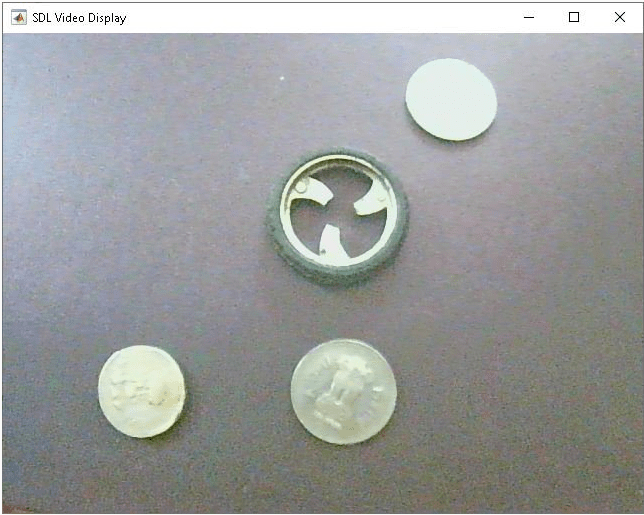
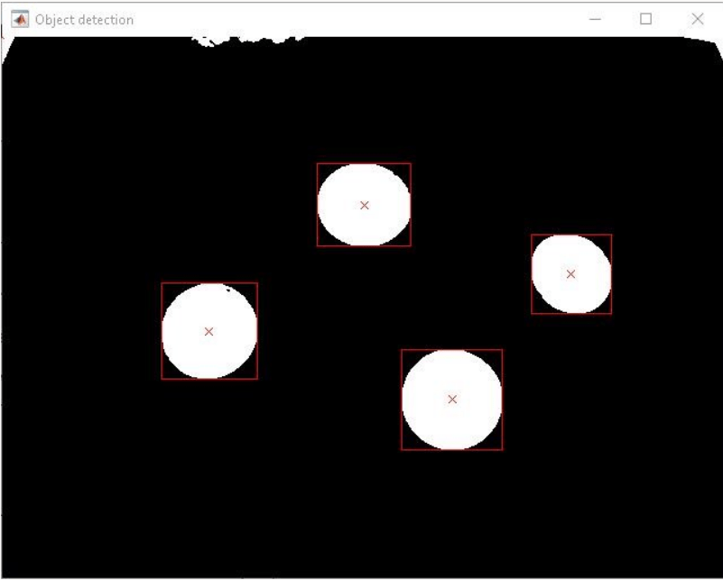
If an object is not detected due to high background noise, change the image properties in the Advanced tab of the V4L2 Video Capture block. For example, when objects are placed in low light, you can increase the brightness to detect the object. Whereas, when objects are placed in bright light, you can decrease the brightness to detect the object. Keep altering the image properties until you can view the object clearly.
![]()
Once the image is clear and the objects can be detected, observe the centroid and bounding box drawn around it.
Other Things to Try
Run the Simulink model in external mode (Monitor and Tune).
Count the number of objects that are detected in the image. Use the parameters such as number of centroids or bounding boxes drawn around the detected objects.
Use the V4L2 Video Capture block properties for an application other than object detection.
You can also select a web site from the following list:
Americas
- América Latina (Español)
- Canada (English)
- United States (English)
Europe
- Belgium (English)
- Denmark (English)
- Deutschland (Deutsch)
- España (Español)
- Finland (English)
- France (Français)
- Ireland (English)
- Italia (Italiano)
- Luxembourg (English)
- Netherlands (English)
- Norway (English)
- Österreich (Deutsch)
- Portugal (English)
- Sweden (English)
- Switzerland
- United Kingdom (English)