MODBUS TCP/IP Communication Between Client and Server Devices Using Raspberry Pi Hardware
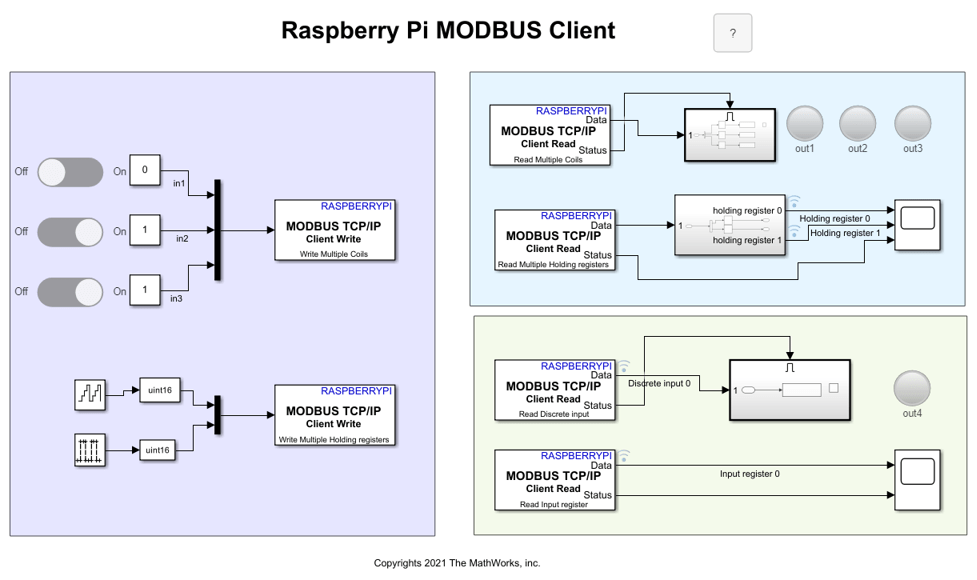
This example shows how to use the Simulink® Support Package for Raspberry Pi® Hardware to implement MODBUS® TCP/IP communication between MODBUS client and server devices. It also shows how to communicate between the two devices in four modes of operation, Client Read, Client Write, Server Read, and Server Write.
This example uses two Raspberry Pi Simulink models, namely Raspberry Pi MODBUS Client and Raspberry Pi MODBUS Server, which together utilize different modes of operation for the client and server devices.
Client Read — Client device reads data from the server device register(s) over TCP/IP
Client Write — Client device writes data to the server device register(s) over TCP/IP
Server Read — Server device reads data from the server device registers over TCP/IP
Server Write — Server device writes data to the server device registers over TCP/IP
The Raspberry Pi MODBUS Server model is deployed on one Raspberry Pi board, while the Raspberry Pi MODBUS Client model runs in external mode on the other Raspberry Pi board.
This table categories the different server device registers referenced by the MODBUS client and server devices.
   Register Type   |   Register Size   |   Allowed Client Operation on Register
-----------------------------------------------------------------------------------
 Coil              |       1-bit       |            Read and Write
 Discrete Input    |       1-bit       |            Read
 Holding Register  |       16-bit      |            Read and Write
 Input Register    |       16-bit      |            Read
Prerequisites
For more information on how to use the Simulink Support Package for Raspberry Pi Hardware to run a Simulink model on Raspberry Pi hardware, see Get Started with Simulink Support Package for Raspberry Pi Hardware.
Required Hardware
Two Raspberry Pi hardware boards
Two USB cables
Configure MODBUS Client Simulink Model and Calibrate Parameters
This support package provides a preconfigured model for the MODBUS client.
Open the raspberrypi_modbus_client Simulink model.
The default values for the Simulink client model are preconfigured in this example depending on the server register size and the allowed client operations. The client write operation is valid on coil and holding registers, whereas the client read operation is valid on all the register types.
For the client mode of operation, configure the IP address of the client Raspberry Pi board in Configuration Parameters > Hardware Implementation > Target hardware resources > Board Parameters.
Configure these parameters in Configuration Parameters > Hardware Implementation > Target hardware resources > Modbus properties.
Set Communication Interface to
TCP/IP.Set Mode to
Client.Configure the server device IP port number in the Remote Server IP port number parameter. In this example, the parameter is set to
502.Set Received timeout (ms) to
100seconds.
Configure MODBUS TCP/IP Client Write Blocks for Coil Registers
To perform the 1-bit write operation on the coil registers, change the position of the slider switches. The On position depicts that data 1 is written on these registers, whereas the Off position depicts that data 0 is written on these registers. Three slider switches are used in this model and their output is multiplexed and fed as an input to the MODBUS TCP/IP Client Write blocks.
Configure these parameters in the MODBUS TCP/IP Client Write Block Parameters dialog box to write data from the slider switches to the coil registers.
Enter the unique IP address of the server device in the Server address parameter. In this model, the parameter is set to
172.19.66.177.Select the
Write Multiple Coilsoption in the Function parameter.To notify the client to write data to two coil registers, specify the address of the first coil in the Coil Address parameter. The default value is
0.Enter
3in the Number of Coils parameter. The default positions of the slider switches areOff,On, andOn.
Configure MODBUS TCP/IP Client Write Blocks for Holding Registers
To perform the 16-bit client write operation on the holding registers, this example uses a counter whose count value increments from 0 to 15 and a pulse generator. The outputs from the free-running counter and the pulse generator are multiplexed and fed as an input to the MODBUS TCP/IP Client Write block.
Configure these parameters in the MODBUS TCP/IP Client Write Block Parameters dialog box to write data from the free-running counter and pulse generator to the holding registers.
Enter the unique IP address of the server device in the Server address parameter. In this model, the parameter is set to
172.19.66.177.Select the
Write Multiple Holding registeroption in the Function parameter.To notify the client to write data to the holding registers, specify the address of the first coil register in the Holding Register Address parameter. The default value is
0.Enter
2in the Number of Holding registers parameter.
Configure these parameters in the Counter Free-Running Block Parameters dialog box.
Enter
4in the Number of bits parameter for the counter to count from 0 to 15.Set the Sample time to
0.1seconds.
Configure these parameters in the Pulse Generator Block Parameters dialog box.
Select the
Sample basedoption in the Pulse type parameter.Set the Sample time to
0.1seconds.
Configure MODBUS TCP/IP Client Read Block for Coil Registers
To perform the 1-bit read operation on the coil registers, three lamp indicators are used to signify the 1-bit read operation from the coil registers. To read this data from the coil registers, configure these parameters in the MODBUS TCP/IP Client Read Block Parameters dialog box.
Enter the unique IP address of the server device in the Server address parameter. In this model, the parameter is set to
172.19.66.177.Select the Read Multiple Coils option in the Function parameter.
To notify the client to read data from coil registers, specify its address in the Coil Address parameter. The default value is
0.Set Number of Coils to
3.Set the Sample Time parameter to
0.1.
Configure MODBUS TCP/IP Client Read Block for Holding Registers
To perform the 16-bit read operation on the holding registers, configure these parameters in the MODBUS TCP/IP Client Read Block Parameters dialog box. The free-running counter and the pulse generator output data that is written on the holding registers can be read using the MODBUS TCP/IP Client Read block. The holding register 0, holding register 1, and the Status outputs can be viewed in the Scope.
Enter the unique IP address of the server device in the Server address parameter. In this model, the parameter is set to
172.19.66.177.Select the Read Multiple Holding registers option in the Function parameter.
To notify the client to read data from coil registers, specify its address in the Holding Register Address parameter. The default value is
0.Set Number of Holding registers to
2.Set the Sample Time parameter to
0.1.
Configure MODBUS TCP/IP Client Read Block for Discrete Input Registers
The data read from the discrete input registers is high when the count value from the free-running counter is greater than or equal to 8. After the count value of 15, the output from the block is reset to 0. This data is valid only if the Status port value is 1, indicating a successful read operation and the presence of valid data on its data port. A lamp indicator is used to signify the 1-bit read from the discrete input register. To perform the 1-bit read operation on the discrete input register, configure these parameters in the MODBUS TCP/IP Client Read Block Parameters dialog box.
Enter the unique IP address of the server device in the Server address parameter. In this model, the parameter is set to
172.19.66.177.Select the Read Discrete input option in the Function parameter.
To notify the client to read data from one discrete input register, specify its address in the Discrete Input Address parameter. The default value is
0.Set the Sample Time parameter to
0.1.
Configure MODBUS TCP/IP Client Read Block for Input Registers
The data read from the input registers is high when the data read from the holding register corresponding to the pulse generator output is low. Similarly, the data read from the input registers is low when the data read from the holding register corresponding to the pulse generator output is high. This data is valid only if the status port value is 1, indicating a successful read operation and the presence of valid data on its data port. Observe the output in the scope. To perform the 16-bit read operation on the input register, configure these parameters in the MODBUS TCP/IP Client Read Block Parameters dialog box.
Enter the unique IP address of the server device in the Server address parameter. In this model, the parameter is set to
172.19.66.177.Select the Read Input register option in the Function parameter.
To notify the client to read data from one input register, specify its address in the Input Register Address parameter. The default value is
0.Set the Sample Time parameter to
0.1.
Configure MODUS Server Simulink Model and Calibrate Parameters
This support package provides a preconfigured model for the MODBUS server.
Open the raspberrypi_modbus_server Simulink model.

The default values for the Simulink server model are preconfigured in this example.
For the server mode of operation, configure the IP address of the server Raspberry Pi board in Configuration Parameters > Hardware Implementation > Target hardware resources > Board Parameters.
Configure these parameters in Configuration Parameters > Hardware Implementation > Target hardware resources > Modbus properties.
Set Communication Interface to
TCP/IP.Set Mode to
Server.Configure the client device IP port number in the Local IP port number parameter. In this example, the parameter is set to
502.Select all the register types. The default Start address and Quantity parameters for these register types are configured as shown in the table:
   Register Type   |   Start Address   |   Quantity
--------------------------------------------------------
 Coil              |         0         |       3
 Discrete Input    |         0         |       1
 Holding Register  |         0         |       2
 Input Register    |         0         |       1
Configure MODBUS TCP/IP Server Read Block for Coil Registers
To perform the 1-bit server read operation on the coil registers, configure these parameters in the MODBUS TCP/IP Server Read Block Parameters dialog box for each coil register.
Select the Read Coil option in the Function parameter.
Set the Coil Address parameter to
0.Set the Sample Time parameter to
0.1.
Similarly, configure the other two MODBUS TCP/IP Server Read blocks and set the Coil Address parameter to 1 and 2, respectively, while the other parameters remain the same.
Double-click the subsystem connected to the Data output port of the MODBUS TCP/IP Server Read block. The Raspberry Pi GPIO Write pins are mapped to the server coil register address. Configure the Raspberry Pi Board and GPIO number parameters.
Configure MODBUS TCP/IP Server Read Block for Holding Registers
To perform the 16-bit server read operation on the holding registers, configure these parameters in the MODBUS TCP/IP server Read Block Parameters dialog box for the free-running counter and the pulse generator output.
Select the Read Holding register option in the Function parameter.
Set the Holding Register Address parameter to
0.Set the Sample Time parameter to
0.1.
Similarly, configure the other MODBUS TCP/IP Server Read blocks and set the Holding Register Address parameter to 1, while the other parameters remain the same.
Configure MODBUS TCP/IP Server Write Block for Discrete Input Registers
Double-click the subsystem connected to the Data output port of the MODBUS TCP/IP Server Read block. The data written in to the discrete input registers is high when the data read from the holding register corresponding to the free-running counter is greater than or equal to 8. After the count value of 15, the output from the block is again reset to 0. This data is valid only if the Status port value is 1, indicating a successful read operation and the presence of valid data on its data port. To perform the 1-bit server write operation on the discrete input register, configure these parameters in the MODBUS TCP/IP Server Write Block Parameters dialog box for the discrete input register.
Select the Write Discrete Input option in the Function parameter.
Set the Discrete Input Address parameter to
0.
Configure MODBUS TCP/IP Server Write Block for Input Registers
Double-click the subsystem connected to the Data output port of the MODBUS TCP/IP Server Read block. The data read written in to the input registers is high when the data read from the holding register corresponding to the pulse generator output is low. Similarly, the data read from the input registers is low when the data read from the holding register corresponding to the pulse generator output is high. This data is valid only if the status port value is 1, indicating a successful read operation and the presence of valid data on its data port. To perform the 16-bit server write operation on the input register, configure these parameters in the MODBUS TCP/IP server Write Block Parameters dialog box for input register.
Select the Write Input Register option in the Function parameter.
Set the Input Register Address parameter to
0
Run MODBUS Simulink Model on Client and Server Devices
1. Connect the Raspberry Pi boards acting as the server device and the client device to the host computer.
2. On the Hardware tab of the Raspberry Pi MODBUS Server Simulink model, in the Mode section, select Run on board and then click Build, Deploy & Start.
3. On the Hardware tab of the Raspberry Pi MODBUS Client Simulink model, in the Mode section, select Run on board and then click Monitor & Tune.
4. For the coil register:
In the MODBUS TCP/IP Client Write block, change the position of the slider switches to write data to the coil registers.
In the MODBUS TCP/IP Client Read block, verify the status of the read operation on the coil registers. Observe the lamp displaying the corresponding data obtained from the coil registers. Verify if the lamp status exhibits the correct data written on the coil registers.
5. For the holding register:
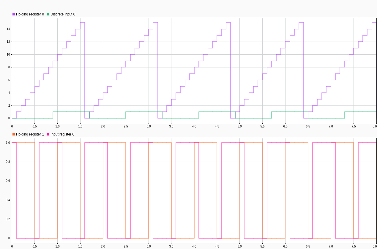
In the MODBUS TCP/IP Client Write block, the counter writes data ranging from 0 to 15 to the holding register 0. Pulses are generated with amplitude 1 and written on the holding register 1.
In the MODBUS TCP/IP Client Read block, check the status of the read operation on the holding registers 0 and 1. Observe the counter value increment from 0 to 15 corresponding to the data obtained from the holding register 0 and verify if the same value is displayed in the scope. Observe the pulse output on the holding register 1 and verify if the same value is displayed in the scope.
6. For the input register:
In the MODBUS TCP/IP Client Read block, check the status of the read operation on the input register. Observe the inverted pulse output corresponding to the data obtained from the pulse generator and compare this value with the data obtained from the holding register 1.
7. For the discrete input register:
In the MODBUS TCP/IP Client Read block, check the status of the read operation on the discrete input register. Observe the pulse output corresponding to the data obtained from the free-running counter and compare this value with the data obtained from the holding register 0.
Simulation Output for MODBUS Client Simulink Model

In the Raspberry Pi MODBUS Client Simulink model, on the Hardware tab, click Data Inspector in the Review Results section to view and map the various outputs from the model. This image maps the outputs of the Holding register 0 versus Discrete Input 0 and Holding register 1 versus Input register 0 for better visibility.
Simulink Data Inspector Output for MODBUS Client Simulink Model
Other Things to Try
Use MODBUS server devices, such as temperature sensors, humidity sensors, and so on, and communicate real-time data to the Raspberry Pi board acting as the client device.
Implement a monitoring system using a PID controller as the server device and the Raspberry Pi board as the client device.