comm.SDRuReceiver
Receive data from USRP device
Add-On Required: This feature requires the Communications Toolbox Support Package for USRP Radio add-on.
Description
The SDRuReceiver
System object™ receives data from a Universal Software Radio Peripheral (USRP™) hardware device, enabling simulation and development for software-defined radio
applications. Use this object to communicate with a USRP board on the same Ethernet subnetwork or a via a USB connection. You can write a
MATLAB® application that uses the System object, or you can generate code for the System object without connecting to a USRP radio.
This object receives signal and control data from a USRP board using the universal hardware driver (UHD™) from Ettus Research™. The System object receives data from a USRP board and outputs a column vector or matrix signal with fixed number of rows.
To receive data from a USRP device:
Create the
comm.SDRuReceiverobject and set its properties.Call the object as if it were a function.
To learn more about how System objects work, see What Are System Objects?.
Note
Starting in R2024a, the MathWorks® products and support packages you require to use this System object depend on your radio device.
| Radio Device | Required MathWorks Products | Support Package Installation |
|---|---|---|
USRP2™ USRP N200, N210 USRP B200, B210 | Communications Toolbox™ Support Package for USRP Radio | Install Communications Toolbox Support Package for USRP Radio |
USRP N300, N310, N320, N321 USRP X300, X310 | Wireless Testbench™ Wireless Testbench Support Package for NI™ USRP Radios | Install Support Package for NI USRP Radios (Wireless Testbench) |
For details on how to use this System object with a radio device supported by Wireless Testbench Support Package for NI
USRP Radios, see comm.SDRuReceiver (Wireless Testbench).
Creation
Description
rx = comm.SDRuReceiver
rx = comm.SDRuReceiver(address)IPAddress property
to address of the connected USRP device.
rx = comm.SDRuReceiver(___,Name = Value) CenterFrequency =
5e6 specifies the center frequency as 5 MHz.
Properties
Unless otherwise indicated, properties are nontunable, which means you cannot change their
values after calling the object. Objects lock when you call them, and the
release function unlocks them.
If a property is tunable, you can change its value at any time.
For more information on changing property values, see System Design in MATLAB Using System Objects.
Connection PropertiesPlatform — Model number of radio
"N200/N210/USRP2" (default) | "B200" | "B210"
Model number of the radio, specified as one of these values.
"N200/N210/USRP2""B200""B210"
Data Types: char | string
IPAddress — IP address of USRP device
"192.168.10.2" (default) | character vector | string scalar
IP address of the USRP device, specified as a character vector or string scalar containing dotted-quad values. When you specify more than one IP address, you must separate each address by commas or spaces.
This value must match the physical IP address of the radio hardware assigned during hardware setup. For more information, see Guided USRP Radio Support Package Hardware Setup. If you configure the radio hardware with an IP address other than the default, update this property accordingly.
To find the logical network location of all connected USRP radios, use the findsdru function.
Example: "192.168.10.2, 192.168.10.5" or "192.168.10.2
192.168.10.5" specifies IP addresses for two devices.
Dependencies
To enable this property, set Platform
to "N200/N210/USRP2".
Data Types: char | string
SerialNum — Serial number of radio
character vector | string scalar
Serial number of the radio hardware, specified as a character vector or string scalar.
This property must match the serial number of the radio hardware assigned during hardware setup. For more information, see Guided USRP Radio Support Package Hardware Setup. If you configure the radio hardware with a serial number other than the default, update this property accordingly.
Dependencies
To enable this property, set Platform to
"B200" or "B210".
Data Types: char | string
ChannelMapping — Channel mapping for radio or bundled radios
1 (default) | positive scalar | row vector of positive values
Channel mapping for the radio or bundled radios, specified as a positive scalar or a row vector of positive values. This table shows the valid values for each radio platform.
Platform Property Value |
ChannelMapping Property Value |
|---|---|
| 1-by-N row vector, where N is
the number of IP addresses in the |
|
|
|
|
When IPAddress contains multiple IP addresses, the
channels defined by ChannelMapping are ordered first by the order in which the IP addresses
appear in the list and then by the channel order within the same radio.
For example, if Platform is "X300" and
IPAddress is "192.168.20.2, 192.168.10.3",
then
ChannelMapping
must be [1 2 3 4]. Channels 1 and 2 of the bundled radio refer to
channels 1 and 2 of the radio with IP address 192.168.20.2, respectively. Channels 3 and
4 of the bundled radio refer to channels 1 and 2 of the radio with IP address
192.168.10.3., respectively.
Data Types: double
CenterFrequency — Center frequency
2.45e9 | nonnegative scalar | row vector of nonnegative values
Center frequency in Hz, specified as a nonnegative scalar or a row vector of nonnegative values. The valid range of values for this property depends on the RF daughter card of the USRP device.
When you have an RF daughtercard, specify the value according to these conditions.
For a single-input single-output (SISO) configuration, specify the value for the center frequency as a nonnegative scalar.
For multiple-input multiple output (MIMO) configurations that use the same center frequency, specify the center frequency as a nonnegative scalar. The center frequency is set by scalar expansion.
For multiple-input multiple output (MIMO) configurations that use different center frequencies, specify the values in a row vector (for example,
[70e6 100e6]). The object applies the ith element of the vector to the ith channel that you specify in theChannelMappingproperty.Note
For a MIMO scenario, the center frequency for a B210 radio must be a scalar. You cannot specify the frequencies as a vector.
Tunable: Yes
Data Types: double
LocalOscillatorOffset — Local oscillator (LO) offset frequency
0 (default) | scalar | row vector
LO offset frequency in Hz, specified as a scalar or row vector. The valid range of this property depends on the RF daughterboard of the USRP device.
The LO offset does not affect the received center frequency. However, the LO offset does affect the intermediate center frequency in the USRP hardware, as this diagram shows.

In this diagram:
f RF is the received RF frequency.
f center is the center frequency that you set in the System object.
f LO offset is the LO offset frequency.
Ideally, fRF - fcenter = 0.
To move the center frequency away from interference or harmonics generated by the USRP hardware, use this property.
To change the LO offset, specify the value according to these conditions.
For a SISO configuration, specify the LO offset as a scalar.
For MIMO configurations, the LO offset must be zero. This restriction is due to a UHD limitation. In this case, you can specify the LO offset as 0.
Tunable: Yes
Data Types: double
Gain — Overall gain for USRP hardware receiver data path
8 (default) | scalar | row vector
Overall gain in dB for the USRP hardware receiver data path, including analog and digital components, specified as a scalar or row vector. The valid range of this property depends on the RF daughterboard of the USRP device.
Specify the gain according to these conditions.
For a SISO configuration, specify the gain as a scalar.
For MIMO configurations that use the same gain value, specify the gain as a scalar. The gain is set by scalar expansion.
For MIMO configurations that use different gains, specify the values in a row vector (for example,
[32 30]). The object applies the ith element of the vector to the ith channel that you specify in theChannelMappingproperty.
Tunable: Yes
Data Types: double
PPSSource — PPS signal source
"Internal" (default) | "External" | "GPSDO"
Pulse per second (PPS) signal source, specified one of these values.
"Internal"— Use the internal PPS signal of the USRP radio."External"— Use the PPS signal from an external signal generator."GPSDO"— Use the PPS signal from a global positioning system disciplined oscillator (GPSDO).
To synchronize the time for all the channels of the bundled radios, you can:
Provide a common external PPS signal to all of the bundled radios and set this property to
"External".Use the PPS signal from each GPSDO that is available on the USRP radio by setting this property to
"GPSDO".
To get the lock
status of the GPSDO to the GPS constellation, set this property to
"GPSDO" and use the gpsLockedStatus function.
Data Types: char | string
EnforceGPSTimeSync — Option to enforce GPS time synchronization
false or 0 (default) | true or 1
Option to enforce GPS time synchronization, specified as one of these values.
1(true) — Synchronize the USRP radio time to the valid global positioning system (GPS) time if the GPSDO is locked to the GPS constellation at the beginning of the transmit or receive operation.0(false) — Set the USRP radio time to the GPSDO time if the GPSDO is not locked to the GPS constellation at the beginning of the transmit or receive operation.
Each time you call the System object, it checks the lock status of the GPSDO. When the GPSDO is locked to the GPS constellation, the System object sets the USRP radio time to the valid GPS time.
Dependencies
To enable this property, set the PPSSource property to
"GPSDO".
Data Types: logical
ClockSource — Clock source
"Internal" (default) | "External" | "GPSDO"
Clock source, specified as one of these values.
"Internal"— Use the internal clock signal of the USRP radio."External"— Use the 10 MHz clock signal from an external clock generator."GPSDO"— Use the 10 MHz clock signal from a GPSDO.
For B-series radios, the external clock port has the label 10 MHz.For N2xx series and USRP2 radios, the external clock port has the label REF IN.
To synchronize the frequency for all the channels of the bundled radios, you can:
Provide a common external 10 MHz clock signal to all of the bundled radios and set this property to
"External".Provide a 10 MHz clock signal from each GPSDO to the corresponding radio and set this property to
"GPSDO".
To synchronize the frequency for all channels, set this property to "GPSDO"
and then verify that the outputs of the referenceLockedStatus and gpsLockedStatus functions both return an output of
1.
Data Types: char | string
MasterClockRate — Master clock rate
positive scalar
Master clock rate in Hz, specified as a positive scalar. The master clock rate is the analog to digital (A/D) and digital to analog (D/A) clock rate. The valid range of values for this property depends on the connected radio platform.
Platform Property Value | MasterClockRate Property
Value (in Hz) |
|---|---|
|
|
| Scalar in the range from
When you use a B210 radio with multiple channels, the clock rate must be less than or equal to 30.72e6. This restriction is a hardware limitation for two-channel operations on B210 radios. The default value is
|
Dependencies
To enable this property, set Platform
to "B200" or
"B210".
Data Types: double
DecimationFactor — Decimation factor for SDRu receiver
512 (default) | integer in the range [1,1024]
Decimation factor for the SDRu receiver, specified as an integer in the range
[1,1024] with restrictions that depend on the radio you use.
DecimationFactor Property Value | B-Series | N2xx-Series |
|---|---|---|
| Valid | Not valid |
| Valid | Valid only when you set the TransportDataTypeproperty to
|
| Valid | Not valid |
Odd integer from 4 to 128 | Valid | Valid |
Even integer in the range
| Valid | Valid |
Integer multiple of 4 in the range
[256,512] | Valid | Valid |
Integer multiple of 8 in the range
| Not valid | Not valid |
The radio uses the decimation factor when it downconverts the intermediate frequency (IF) signal to a complex baseband signal.
Data Types: double
EnableTimeTrigger — Option to enable timed transmission and reception
0 or false (default) | 1 or true
Option to enable timed transmission and reception, specified as a numeric or logical
value of 1 (true) or 0
(false). When you set this property to 1
(true), you can:
Transmit or receive after the time specified in the
TriggerTimeproperty.Transmit or receive at the specified GPS time in the
TriggerTimeproperty if you set thePPSSourceproperty to"GPSDO".Simultaneously transmit and receive after the time specified in the
TriggerTimeproperty.
Data Types: logical
TriggerTime — Trigger time in seconds
5 (default) | nonnegative scalar
Trigger time in seconds, specified as a nonnegative scalar. Specify the trigger time
after which the radio starts transmitting or receiving data. The
TriggerTime value must be greater than the current USRP radio time. Use the getRadioTime function to get the current USRP radio time.
Note
After you call the getRadioTime function, call the System
object before releasing it to ensure that the object is released properly.
When you set the PPSSource property to
"GPSDO", specify the TriggerTime property
as the exact GPS time in seconds at which you want the radio to start transmitting or
receiving data.
Note
For AD936x-based B2xx series USRP radios, you can expect a consistent delay between the specified trigger time and the start of transmission or reception.
Dependencies
To enable this property, set the EnableTriggerTime property
to true.
Data Types: double
TransportDataType — Transport data type
"int16" (default) | "int8"
Transport data type, specified as one of these values:
"int16"— Use 16-bit transport to achieve higher precision."int8"— Use 8-bit transport to achieve a transport data rate that is approximately two times faster than 16-bit transport. The quantization step is 256 times larger than 16-bit transport.
The default transport data type assigns the first 16 bits to the in-phase (I) component and the remaining16 bits to the quadrature (Q) component, resulting in 32 bits for each complex sample of transport data.
Data Types: char | string
OutputDataType — Data type of output signal
"Same as transport data type" (default) | "double" | "single"
Data type of the output signal, specified as one of these values.
"Same as transport data type"— Set the output data type to the same as the transport data type: eitherint8orint16.When the transport data type is
int8, the output values are raw 8-bit I and Q samples from the board in the range [–128, 127].When the transport data type is
int16, the output values are raw 16-bit I and Q samples from the board in the range [–32 768 32 767].
"single"— Specify single-precision floating point values scaled to the range [–1, 1]."double"— Specify double-precision floating point values scaled to the range [–1, 1].
Data Types: char | string
Complex Number Support: Yes
SamplesPerFrame — Number of samples per frame
362 (default) | positive integer
Number of samples per frame of the output signal, specified as a positive integer. This value optimally uses the underlying Ethernet packets, which have a size of 1500 8-bit bytes.
Note
Starting in R2021b, the limitation on setting the SamplesPerFrame property to a maximum value of
375000 is removed. You can set this property to any positive
integer value.
Data Types: double
EnableBurstMode — Option to enable burst mode
0 or false (default) | 1 or true
Option to enable burst mode, specified as a numeric or logical value of
1 (true) or 0
(false). To produce a set of contiguous frames without an overrun
or underrun to the radio, set this property to 1
(true). Enable burst mode to simulate models that cannot run in
real time.
When you enable burst mode, specify the number of frames in a burst by using the
NumFramesInBurst property. For more
information, see Detect Underruns and Overruns.
Data Types: logical
NumFramesInBurst — Number of frames in a contiguous
burst
1 (default) | nonnegative integer
Number of frames in a contiguous burst, specified as a nonnegative integer.
Dependencies
To enable this property, set EnableBurstMode to 1
(true).
Data Types: double
Usage
Syntax
Description
data = rx()comm.SDRuReceiver
System object, rx.
[ also returns the timestamp of each received sample from a USRP
device.data,dataLen,overrun,timeStamps]
= rx()
Output Arguments
Object Functions
To use an object function, specify the
System object as the first input argument. For
example, to release system resources of a System object named obj, use
this syntax:
release(obj)
Examples
Receive Signals with B210 Radio and SDRu Receiver System Object
Configure a B210 radio with a serial number B312. Set the radio to receive at 2.5 GHz with a decimation factor of 256.
Create an SDRu Receiver System object for data reception.
rx = comm.SDRuReceiver(...
              Platform ="B210", ...
              SerialNum ="B312", ...
              CenterFrequency =2.5e9, ...
              MasterClockRate =56e6, ...
              DecimationFactor =256);
Save the valid data using the dsp.SignalSink System object.
rxLog = dsp.SignalSink;
    for counter = 1:20
        data = rx();
        rxLog(data);
    end
release(rx)
release(rxLog)
Get Radio Information for Multichannel Radio
Create an SDRu receiver System object for a multichannel radio configuration.
radio = comm.SDRuReceiver(Platform ="X300",IPAddress ='192.168.60.2');
radio.ChannelMapping = [1 2];
radio.CenterFrequency = [1.2 1.3]*1e9;
radio.Gain = [5 6];
Get the radio information by calling the info function.
info(radio)
ans = struct with fields:
                    Mboard: 'X300'
                  RXSubdev: {'UBX RX'  'UBX RX'}
                  TXSubdev: {'UBX TX'  'UBX TX'}
    MinimumCenterFrequency: [-70000000 -70000000]
    MaximumCenterFrequency: [6.0800e+09 6.0800e+09]
               MinimumGain: [0 0]
               MaximumGain: [37.5000 37.5000]
                  GainStep: [0.5000 0.5000]
           CenterFrequency: [1.2000e+09 1.3000e+09]
     LocalOscillatorOffset: 0
                      Gain: [5 6]
           MasterClockRate: 200000000
          DecimationFactor: 512
        BasebandSampleRate: 390625
Capture and Save Receive Signals to Baseband File Writer
Configure a B200 radio with an IP address set to 30FD838. Set the radio to receive at 1 GHz with a decimation factor of 512 and a master clock rate of 56 MHz.
Create an SDRu Receiver System object for data reception. Calculate the baseband sample rate by using the master clock rate and decimation factor.
rx = comm.SDRuReceiver(...
              Platform ="B200", ...
              SerialNum ="30FD838", ...
              CenterFrequency =1e9, ...
              MasterClockRate =56e6, ...
              DecimationFactor =512);
sampleRate = rx.MasterClockRate/rx.DecimationFactor;
Create a baseband file writer object with a center frequency of 1 GHz.
rxWriter = comm.BasebandFileWriter('b200_capture.bb', ...
         sampleRate,rx.CenterFrequency);
Write the valid baseband data to 'b200_capture.bb'.
for counter = 1:2000
    data = rx();
    rxWriter(data);
end
Display information about the received signal. Release the System objects.
info(rxWriter);
release(rx);
release(rxWriter);
Detect Lost Samples Using SDRu Receiver System Object
Configure a B200 radio with serial number 30FD838. Set the radio to receive at 2.5 GHz with a decimation factor of 125, the output data type to double and master clock rate of 56 MHz.
Create a USRP radio receiver System object for data reception.
rx = comm.SDRuReceiver(Platform ="B200", ...
         SerialNum ="30FD838", ...
         CenterFrequency =2.5e9, ...
         MasterClockRate =56e6, ...
         DecimationFactor =125, ...
         OutputDataType ="double");
Capture signal data using comm.DPSKDemodulator System object.
demodulator = comm.DPSKDemodulator(BitOutput =true);
Inside a for-loop, receive the data using the rx System object and it returns overrun as an output argument. With SRDu receiver System objects, the overrun output indicates data loss. This output is a useful diagnostic tool for determining real-time operation of the System object. Display the messages when the receiver indicates an overrun with data loss.
for frame = 1:2000
    [data,overrun] = rx();
    demodulator(data);
      if overrun ~= 0
         msg = ['Overrun detected in frame #',int2str(frame)];
      end
end
release(rx)
Burst-Mode Buffering to Overcome Overruns at Receiver
Configure a B200 radio with serial number 30FD838. Set the radio to receive at 2.5 GHz with a decimation factor of 125 and master clock rate of 56 MHz. Enable burst-mode buffering to overcome overruns. Set the number of frames in a burst to 20 and the number of samples per frame to 37500.
Create an SDRu receiver System object to use for data reception.
rx = comm.SDRuReceiver(...
               Platform ="B200", ...
              SerialNum ="30FD838", ...
              CenterFrequency =2.5e9, ...
              MasterClockRate =56e6, ...
              DecimationFactor =125, ...
              OutputDataType ="double");
rx.EnableBurstMode = true;
rx.NumFramesInBurst = 20;
rx.SamplesPerFrame = 37500;
Capture signal data using comm.DPSKDemodulator System object.
demodulator = comm.DPSKDemodulator(BitOutput =true);
Inside a for-loop, receive the data using the rx System object.
numFrames = 100;
for frame = 1:numFrames
    [data,overrun] = rx();
      if ~(overrun)
         demodulator(data);
      end
end
release(rx)
Get Timestamps of Received Signal Using SDRu Receiver System Object
Configure a B210 radio with the serial number 3136D5F. Set the PPS signal source to the PPS signal from a GPSDO and enable GPS time synchronization. Set the clock source to GPSDO. Set the master clock rate to 20MHz, decimation factor to 20, and number of received samples per frame to 10.
Create an SDRu receiver System object to receive data form the USRP™ device.
format long;
rx = comm.SDRuReceiver(Platform = "B210", SerialNum='3136D5F', ...
                       PPSSource = "GPSDO", EnforceGPSTimeSync = true, ...
                       ClockSource= "GPSDO", ...
                       MasterClockRate=20e6, DecimationFactor=200, ...
                       SamplesPerFrame = 20000);
Check the GPS lock status.
GPSLockStatus = 0;
while ~GPSLockStatus
    disp("Trying to lock to GPS constellation ...");
    GPSLockStatus =  gpsLockedStatus(rx);
end
Trying to lock to GPS constellation ...
if GPSLockStatus
    disp("GPSDO is locked. Acquiring data from radio ...");
    [data,~, ~,GPSTimestamps] = rx();
    d = datetime(GPSTimestamps(1), 'convertfrom', 'posixtime', 'Format', 'MM/dd/yy HH:mm:ss.SSS','TimeZone','Asia/Calcutta');
end
GPSDO is locked. Acquiring data from radio ...
USRP time synchronized to GPS time
Release the System object. Display the GPS timestamp of the first received data sample.
release(rx);
fprintf('GPS timestamp of first sample: %s',d);
GPS timestamp of first sample: 07/27/23 16:33:38.078
Receive Phase Synchronized Signals Using TwinRX Daughterboard
Receive phase synchronized signals using the TwinRX daughterboard. Transmit the sinusoidal signals with a B210 radio and receive the signals on an X300 radio with two TwinRX daughterboards. This example requires two MATLAB sessions running on your host computer.
To run this example, you require:
300-Series USRP radio (X3xx) and Wireless Testbench Support Package for NI USRP Radios. For information on mapping an NI USRP device to an Ettus Research 300-series USRP device, see Supported Radio Devices (Wireless Testbench) (Wireless Testbench).
200-Series USRP radio (B2xx or N2xx) and Communications Toolbox Support Package for USRP Radio, required when using the radio as the transmitter. For information on mapping an NI™ USRP device to an Ettus Research 200-series USRP device, see Supported Hardware and Required Software.
In the first MATLAB session, configure a B210 radio with the serial number 31B92DD. Set the radio to transmit at 2.45 GHz with an interpolation factor of 100, and a master clock rate of 61.44 MHz. Specify a gain of 60 dB and transport data type of int16.
tx = comm.SDRuTransmitter(...
                    Platform ="B210", ...
                    SerialNum = "31B92DD", ...
                    MasterClockRate = 61.44e6, ...
                    InterpolationFactor = 100, ...
                    Gain = 60, ...
                    CenterFrequency = 2.45e9, ...
                    TransportDataType = "int16");
Generate a sine wave with a frequency of 30 kHz for transmission. Calculate the sample rate by using the master clock rate and interpolation factor for an B210 radio System object configuration. Set the output data type of the sine wave to double.
sinewave = dsp.SineWave(1,30e3);
sinewave.SampleRate = 100e6/100;
sinewave.SamplesPerFrame = 5e4;
sinewave.OutputDataType = 'double';
sinewave.ComplexOutput = true;
data = step(sinewave);
Set the frame duration for the transmission based on the samples per frame and sample rate. Create time scope and frequency scope System objects to display time-domain and frequency-domain signals, respectively. Display a message when transmission starts.
frameDuration = (sinewave.SamplesPerFrame)/(sinewave.SampleRate);
time = 0;
timeScope = timescope(TimeSpanSource = "Property", TimeSpan = 4/30e3,...
                      SampleRate = 100e6/100);
spectrumScope = dsp.SpectrumAnalyzer('SampleRate',sinewave.SampleRate);
disp("Transmission Started");
timeScope(data);
spectrumScope(data);
Inside a while-loop, transmit the sine wave using the tx System object. Display a message when transmission is complete. Release the radio System object.
while time < 30
    tx(data);
    time = time+frameDuration;
end
disp("Transmission Stopped");
release(tx);
In the second MATLAB session, configure an X300 radio with an IP address of 192.168.20.2. Set the radio to receive at 2.45 GHz with a decimation factor of 200 and a master clock rate of 200 MHz. Enable the TwinRX daughterboard and the TwinRX phase synchronization capability to receive phase synchronized signals. Set the ChannelMapping property to [1 2 3 4]. Connect the power splitter from an B210 transmitter to four receiver channels of the X300 radio for calibration.
rx = comm.SDRuReceiver(Platform = "X300", ...
                    IPAddress = '192.168.20.2', ...
                    OutputDataType = "double", ...
                    IsTwinRXDaughterboard = true, ...
                    EnableTwinRXPhaseSynchronization = true, ...
                    ChannelMapping = [1 2 3 4], ...
                    MasterClockRate = 200e6, ...
                    DecimationFactor = 200, ...
                    Gain = 70, ...
                    CenterFrequency = 2.45e9, ...
                    SamplesPerFrame = 4000);
Set the frame duration for the signal reception based on the samples per frame and sample rate. Create time scope and frequency scope System objects to display time-domain and frequency-domain signals, respectively. Display a message when reception starts.
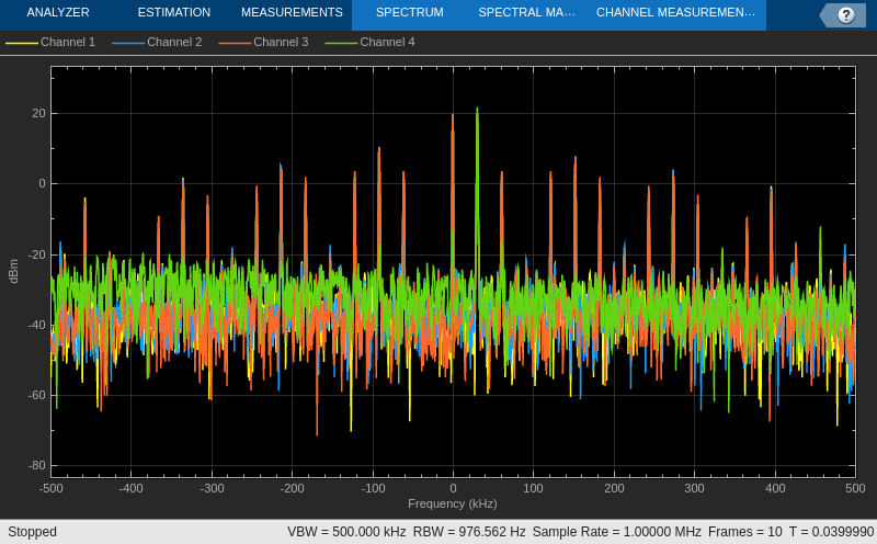
frameduration = (rx.SamplesPerFrame)/(200e6/200);
time = 0;
timeScope = timescope(TimeSpanSource = "Property",...
                      TimeSpan = 4/30e3,SampleRate = 200e6/200);
spectrumScope = dsp.SpectrumAnalyzer('SampleRate',200e6/200);
spectrumScope.ReducePlotRate = true;
disp("Reception Started");
Reception Started
Inside a while-loop, receive the sine wave using the rx System object. Normalize the signal with respect to the amplitude for each receive channel. Compute the fast Fourier transform (FFT) of each normalized signal. Calculate the phase difference between channels 1 and 2, channels 1 and 3, and channels 1 and 4. Display the phase difference between channel 1 and each of the other channels of the TwinRX daughterboard.
counter = 0;
while time < 10 && counter < 10
 data = rx();
    amp(1) = max(abs(data(:,1)));
    amp(2) = max(abs(data(:,2)));
    amp(3) = max(abs(data(:,3)));
    amp(4) = max(abs(data(:,4)));
    maxAmp = max(amp);
    if any(~amp)
       normalizedData = data;
    else
      normalizedData(:,1) = maxAmp/amp(1)*data(:,1);
      normalizedData(:,2) = maxAmp/amp(2)*data(:,2);
      normalizedData(:,3) = maxAmp/amp(3)*data(:,3);
      normalizedData(:,4) = maxAmp/amp(4)*data(:,4);
    end
    freqOfFirst = fft(normalizedData(:,1));
    freqOfSecond = fft(normalizedData(:,2));
    freqOfThird = fft(normalizedData(:,3));
    freqOfFourth = fft(normalizedData(:,4));
    angle1 = rad2deg(angle(max(freqOfFirst)/max(freqOfSecond)));
    angle2 = rad2deg(angle(max(freqOfFirst)/max(freqOfThird)));
    angle3 = rad2deg(angle(max(freqOfFirst)/max(freqOfFourth)));
    timeScope([real(normalizedData),imag(normalizedData)]);
    spectrumScope(normalizedData);
    time = time + frameduration;
    counter = counter +1;
    disp([' Phase difference between channel 1 and 2: ', num2str(angle1)]);
    disp([' Phase difference between channel 1 and 3: ', num2str(angle2)]);
    disp([' Phase difference between channel 1 and 4: ', num2str(angle3)]);
    disp(' ');

end
Phase difference between channel 1 and 2: 22.7838
Phase difference between channel 1 and 3: 159.7515
Phase difference between channel 1 and 4: -136.388
Phase difference between channel 1 and 2: 22.7311
Phase difference between channel 1 and 3: 159.9299
Phase difference between channel 1 and 4: -136.2448
Phase difference between channel 1 and 2: 22.7629
Phase difference between channel 1 and 3: 160.0174
Phase difference between channel 1 and 4: -136.2094
Phase difference between channel 1 and 2: 22.8828
Phase difference between channel 1 and 3: 159.9154
Phase difference between channel 1 and 4: -136.3182
Phase difference between channel 1 and 2: 22.8373
Phase difference between channel 1 and 3: 160.068
Phase difference between channel 1 and 4: -136.2829
Phase difference between channel 1 and 2: 22.911
Phase difference between channel 1 and 3: 160.032
Phase difference between channel 1 and 4: -136.1785
Phase difference between channel 1 and 2: 22.8487
Phase difference between channel 1 and 3: 160.069
Phase difference between channel 1 and 4: -136.2131
Phase difference between channel 1 and 2: 22.8922
Phase difference between channel 1 and 3: 159.9904
Phase difference between channel 1 and 4: -136.2636
Phase difference between channel 1 and 2: 22.8615
Phase difference between channel 1 and 3: 160.0293
Phase difference between channel 1 and 4: -136.2306
Phase difference between channel 1 and 2: 22.8312
Phase difference between channel 1 and 3: 160.0191
Phase difference between channel 1 and 4: -136.4391
release(timeScope);

release(spectrumScope);
release(rx);
disp("Reception ended");
Reception ended
FMCW Radar Waveform Based Range Calculation Using Time Trigger
This example shows how to use time triggering with a B210 radio to calculate the range of a target using frequency-modulated continuous wave (FMCW) radar waveform.
Generate FMCW radar waveform
Set the sample rate, interpolation factor or decimation factor, and master clock rate.
Fs = 30e6; % Sample Rate
interpDecim  = 1; % Interpolation or Decimation factor of interest
masterClkRate = interpDecim*Fs; % Master clock rate
Set the sweep time and sweep bandwidth. Divide the sweep bandwidth by the sweep time to obtain the slope.
% Specify sweep time and sweep bandwidth
sweepTime = 1e-3;
sweepBW = 15e6;
slope = sweepBW/sweepTime;
Use the bw2rangeres (Phased Array System Toolbox) function to calculate the range resolution corresponding to the signal bandwidth and the time2range (Phased Array System Toolbox) function to calculate the maximum range the signal propagates during sweepTime/6 seconds.
% Calculate the range resolution and maximum range
rangeRes = bw2rangeres(sweepBW);
fprintf('Range resolution = %d',rangeRes)
Range resolution = 9.993082e+00
maxRange  = time2range(sweepTime/6);
fprintf('Maximum range = %d',maxRange)
Maximum range = 2.498270e+04
Create a phased.FMCWWaveform (Phased Array System Toolbox) object.
hwav = phased.FMCWWaveform(SampleRate=Fs, SweepTime=sweepTime,...
                           SweepBandwidth=sweepBW, OutputFormat='Sweeps', NumSweeps=1);
Generate the FMCW radar waveform.
xRef =  hwav();
NumSamps = length(xRef);
Set Transmitter Properties
Create a comm.SDRuTransmitter object.
txGain = 45;
txChannelMapping = 1;

tx = comm.SDRuTransmitter(Platform = "B210", SerialNum='3136D5F', ...
    PPSSource = "Internal", ...
    ClockSource= "Internal", ...
    MasterClockRate=masterClkRate,...
    InterpolationFactor=interpDecim,...
    ChannelMapping=txChannelMapping,...
    Gain=txGain, CenterFrequency=3.21e9);
Set the EnableTimeTrigger property for the transmitter object as true and set the desired trigger time for transmission.
% Provide trigger time
usrpTriggerTime = 12;

tx.EnableTimeTrigger = true;
tx.TriggerTime = usrpTriggerTime;
Set Receiver Properties
Create a comm.SDRuReceiver object.
rxGain = 45;
rxChannelMapping = 2;

rx = comm.SDRuReceiver(Platform = "B210", SerialNum='3136D5F', ...
    PPSSource = "Internal", ...
    ClockSource= "Internal", ...
    MasterClockRate=masterClkRate,...
    DecimationFactor=interpDecim, ...
    SamplesPerFrame = NumSamps,...
    OutputDataType="double",...
    ChannelMapping=rxChannelMapping, Gain=rxGain,CenterFrequency=3.21e9);
Set the EnableTimeTrigger property for the receiver object as true and set the desired trigger time for reception.
rx.EnableTimeTrigger = true;
rx.TriggerTime = usrpTriggerTime; % Same as tx trigger time
Set Timescope and Spectrumscope properties
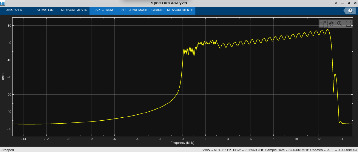
Set the spectrumAnalyzer and timescope properties.
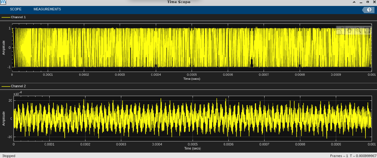
decimfact = 4;
spectrumScope1 = spectrumAnalyzer(SampleRate=Fs);
spectrumScope2 = spectrumAnalyzer(SampleRate=Fs/decimfact);
spectrumScope3 = spectrumAnalyzer(SampleRate=Fs/decimfact);

spectrumScope2.PeakFinder.Enabled = true;
spectrumScope3.PeakFinder.Enabled = true;

% Set the number of frames you would like to process
numFrames = 1;
frameTime = NumSamps/Fs;
timeSpan = numFrames*frameTime;

timeScope = timescope(SampleRate=Fs, ...
    TimeSpanSource="property", ...
    TimeSpan = timeSpan, ...
    LayoutDimensions=[2,1]);
Transmit and Receive FMCW Radar Waveform
Transmit the FMCW radar waveform and receive the reflected FMCW radar waveform from the target after the specified trigger time.
yBuff = zeros(numFrames*NumSamps,1);
xRefBuff = zeros(numFrames*NumSamps,1);

for i=1:numFrames
    txData = hwav();
    underrun = tx(txData);
    if underrun==0
        disp('Transmission successful')
    else
        disp('Transmission failed')
    end
    % Receive the signal

    [rxdata, ~,overflow, rx_time_stamp] = rx();
    if overflow==0
        disp('Reception successful')
    else
        disp('Reception failed')
    end
    yDechirp = dechirp(rxdata,txData);
    yBuff((i-1)*NumSamps+1:i*NumSamps,1) = yDechirp;

    xRefBuff((i-1)*NumSamps+1:i*NumSamps,1) = txData;

    spectrumScope1(txData)
    spectrumScope2(decimate(yDechirp,decimfact))
end
Transmission successful
Reception successful
 Calculate the Range of the Target Based On the Beat Frequency
To calculate the beat frequency, use spectrum analyzer to find the peak frequency.
spectrumData1 = getMeasurementsData(spectrumScope2);
beatFreq = spectrumData1.PeakFinder.Frequency(1);
c = 3e8; % Speed of light
beatFreqRange = beat2range(beatFreq,slope,c);
fprintf('Range of the target based on beat frequency = %d',beatFreqRange)
Range of the target based on beat frequency = 8.056641e+02
timeScope(real(xRefBuff),real(yBuff));
 Release the timescope, spectrumscope, transmitter and receiver System objects.
release(timeScope);
release(spectrumScope1);
release(spectrumScope2);
release(rx);
release(tx);
Generate MEX Function from MATLAB Function Using SDRu Receiver System Object
This example shows how to generate a MEX file called
sdruReceiveMex from the function sdruReceiveData.
When you run this MEX file, the code shows a performance improvement and no overruns for
data frames that contain 10000 samples.
Create a function that configures comm.SDRuReceiver System object.
Set the frame duration for the radio to receive data based on samples per frame and
sample rate. Display a message when reception starts. Inside a
for-loop, receive the data using the rx System
object and return the overrun output argument.
function [receiveTime,overrunCount] = sdruReceiveData()
        duration = 10;
        masterClockRate = 35e6;
        decimationFactor = 1;
        samplesPerFrame = 10000;

        sampleRate = masterClockRate/decimationFactor;
        frameDuration = samplesPerFrame/sampleRate;
        iterations = duration/frameDuration;

        rx = comm.SDRuReceiver(Platform = "B210",SerialNum = "30F59A1", ...
                       MasterClockRate = masterClockRate, ...
                       DecimationFactor = decimationFactor, ...
                       OutputDataType = "double");
        count = 0;
        rx();
        disp("Started Reception...");
        tic
        for i = 1:iterations
            [data,~,overrun] = rx();
            if overrun
            count = count + 1;
            end
        end
        receiveTime = toc;
        overrunCount = count;
        release(rx);
        end
Generate a MEX file with the name sdruReceiveMex from the
function sdruReceiveData.
codegen sdruReceiveData -o sdruReceiveMex;
Run this MEX file to receive data using the generated MEX and observe the reception time and number of overruns.
[ReceiveTime,overrunCount] = sdruReceiveMex()
More About
Extended Capabilities
Version History
Introduced in R2011bSee Also
Objects
Blocks
Functions
You can also select a web site from the following list:
Americas
- América Latina (Español)
- Canada (English)
- United States (English)
Europe
- Belgium (English)
- Denmark (English)
- Deutschland (Deutsch)
- España (Español)
- Finland (English)
- France (Français)
- Ireland (English)
- Italia (Italiano)
- Luxembourg (English)
- Netherlands (English)
- Norway (English)
- Österreich (Deutsch)
- Portugal (English)
- Sweden (English)
- Switzerland
- United Kingdom (English)