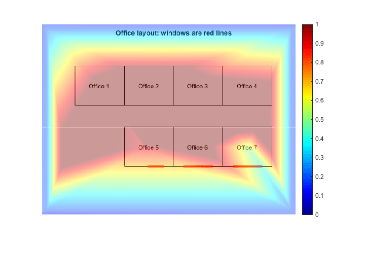
创建热图叠加图像
此示例展示了如何使用来自 ESP32 开发板的无线网络信号强度测量来创建热图。
ThingSpeak™ 通过在图像或地图上投射测量值来帮助您可视化数据。您不需要特殊的硬件,但您需要区域和位置测量的图像。有关更多信息,请参阅 Arduino 中使用 ESP32 的无线网络信号强度。
创建 MATLAB® Visualization
选择 Apps > MATLAB Visualization。然后选择 New,接着选择 Custom (no starter code) 并点击 Create。

收集数据
将 X 和 Y 坐标以及信号强度保存在单独的向量中。您可以从 ThingSpeak 通道读取信号强度的数据。将 CHANNEL_ID, READ_API_KEY 和 FIELD_NUMBER 替换为您通道中的适当值。您可以在通道主页顶部找到您的通道 ID。您可以在通道视图的 API Keys 选项卡中找到 API 密钥。
% Enter data by hand if data from a ThingSpeak channel is not available.
strength = [-90 -90 -90 -90 -40 -20 -22.4 -45 -35 -41 -44 -55 -40 -75 -26]';
% Read data from a ThingSpeak channel.
% Uncomment the next line to read from ThingSpeak.
% strength = thingSpeakRead(CHANNEL_ID, ReadKey',READ_API_KEY,'numPoints',15,'fields',FIELD_NUMBER');
X = [10 550 550 10 50 234 393 129 237 328 448 225 344 457 477]';
Y = [10 10 410 410 293 210 202 132 130 142 141 272 268 274 200]';
将无线信号测量值转换为百分比。
strengthPercent = 2*(strength+100)/100;
读图
存储图像的尺寸。您的图像必须托管在网络上。
[I,m] = imread('https://www.mathworks.com/help/examples/thingspeak/win64/CreateHeatmapOverlayImageTSExample_02.png','png');
picture=ind2rgb(I,m);
[height,width,depth] = size(picture);

创建模型
插入现有点并使用插值结果填充覆盖图像。然后设置覆盖的透明度。
OverlayImage=[];
F = scatteredInterpolant(Y, X, strengthPercent,'linear');
for i = 1:height-1
   for j = 1:width-1
          OverlayImage(i,j) = F(i,j);
   end
end
alpha = (~isnan(OverlayImage))*0.4;
显示图像和颜色条
最后,用颜色条显示图像。将颜色限制设置为与数据值相关。将 AlphaData 设置为之前创建的透明度矩阵。
imshow(picture,m);
hold on

h = imshow(OverlayImage);

colormap(h.Parent, jet);
colorbar(h.Parent);
set(h,'AlphaData',alpha);

最终结果分别用红色和蓝色表示信号强度最高和最低的区域。
另请参阅
MATLAB Analysis App | MATLAB 可视化 App | 使用 Arduino IDE 测量 ESP32 的无线网络信号强度 | Write Data | thingSpeakRead