Verify Frequency of PLLRAW Clock Using IO Device Builder App
This example shows how to use the IO Device Builder app to verify the frequency of the PLLRAW clock. This example uses XTAL clock as a reference clock for verifying the frequency. For clock verification, Dual Clock Comparator (DCC) module 0 is utilized.
The DCC module is used in validating the integrity and performance of clock signals within a system.
The DCC module takes two clock inputs: the clock signal under test and a reference clock signal. The reference clock is typically a highly stable and accurate clock source.
The primary function of the DCC module is to detect any deviations or discrepancies between these two clock signals.
The XTAL clock, serving as the reference clock at 20MHz, is compared against the PLLRAW clock, which needs to be verified and is expected to operate at 120MHz.
Prerequisites
Ensure that C2000Ware is installed as recommended by hardware setup screens for C2000™ Microcontroller Blockset. For more information, see Hardware Setup for C2000 Microcontroller Blockset.
Note: No circuit connections are required for this example.
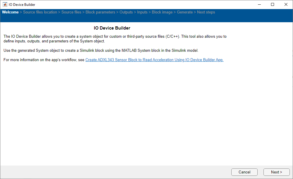
Open the IO Device Builder App
To open the IO Device Builder app, perform these steps.
Start MATLAB® and then open / create a Simulink® model.
Go to Modeling > Model Settings to open the Configuration Parameters dialog box.
Open the Hardware Implementation pane, and select a Texas Instruments™ C2000 board, which supports DCC module. This example uses TI F28003x board.
On the Hardware tab of the Simulink toolstrip, in Prepare section, under Design, choose IO Device Builder.
Select Working Directory and Add Third-Party Source Files
Once the Source files location page loads, select the working directory and add third-party source files.

On the Source files location page:
Click Select and select the working directory. In the working directory, the generated system object, along with the corresponding
.cppand.hfiles, and the model are located.Click Add folder and add the folders where third-party
.c/.hfiles are present. Only the files present directly within the selected folder are included, and any files present within subfolders are excluded.Click Next to continue.
Select Source Files

On the Source files page, select the dcc.c driver file and then click Next to continue.
Specify Block Parameters
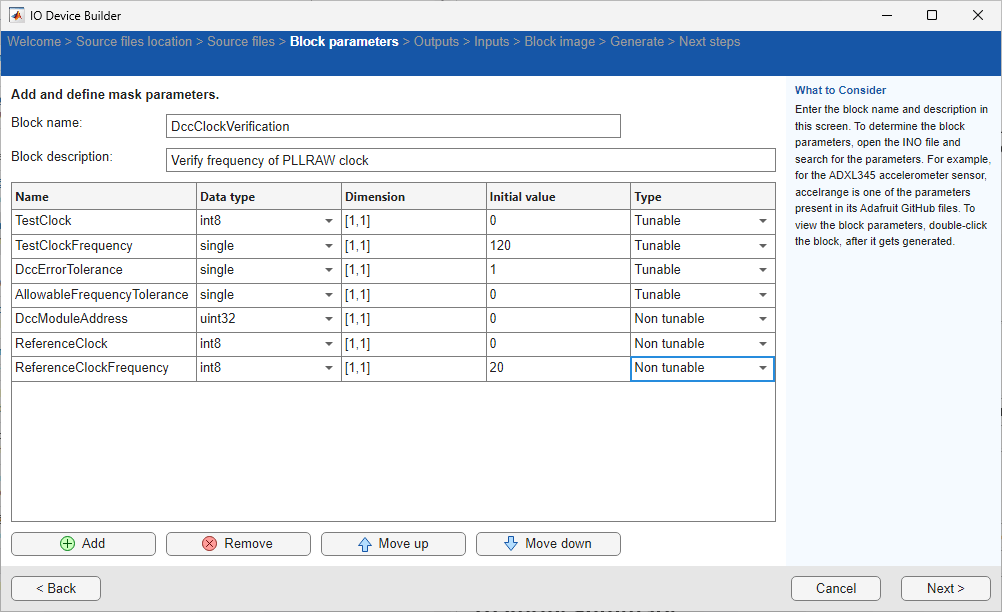
On the Block parameters page:
1. Specify the block name and add block description.
2. Add the following mask parameters for the block. Depending on the requirements of a particular system or application, set parameters as tunable or non tunable.
This example uses these tunable and non tunable parameters.
Tunable Parameters: Set the following tunable parameters to allow tuning while the model is running.
TestClock: Data type:
uint8,Initial value: 0TestClockFrequency: Data type:
single,Initial value: 120DccErrorTolerance: Data type:
single,Initial value: 1AllowableFrequencyTolerance: Data type:
single,Initial value: 0
Non tunable Parameters:
DccModuleAddress: Data type: u
int32,Initial value: 0ReferenceClock: Data type:
uint8,Initial value: 0ReferenceClockFrequency: Data type:
single,Initial value: 20
3. Click Next to continue.
Select Outputs for the Block
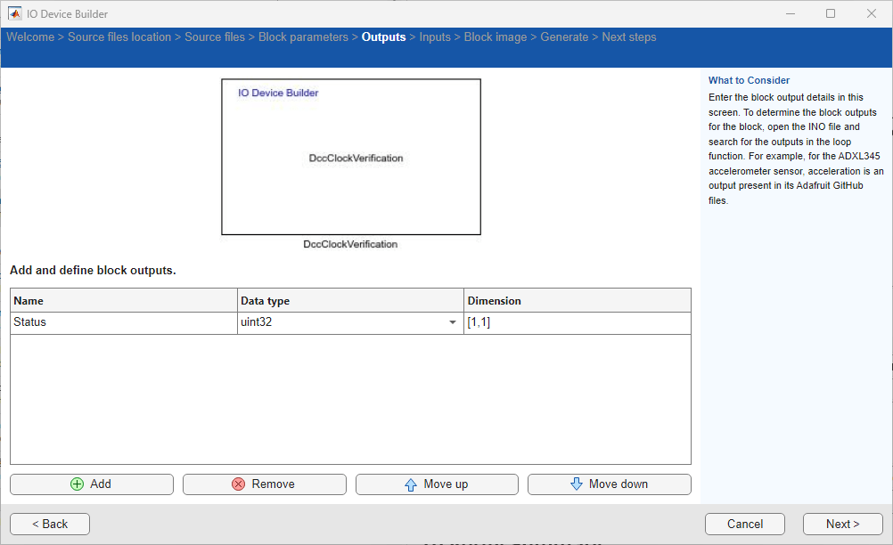
On the Outputs page:
Add Output port as
Statusand set data type asuint32and Dimension as[1,1].Click Next to continue.
Select Inputs for the Block
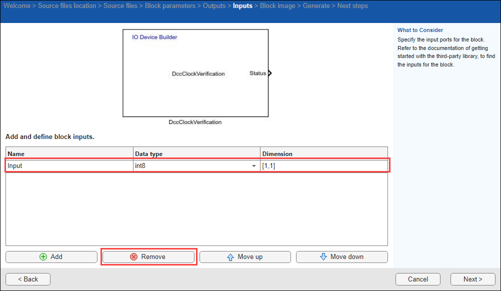
On the Inputs page:
Remove inputs for the block, if any already added.
Click Next to continue.
Preview Block
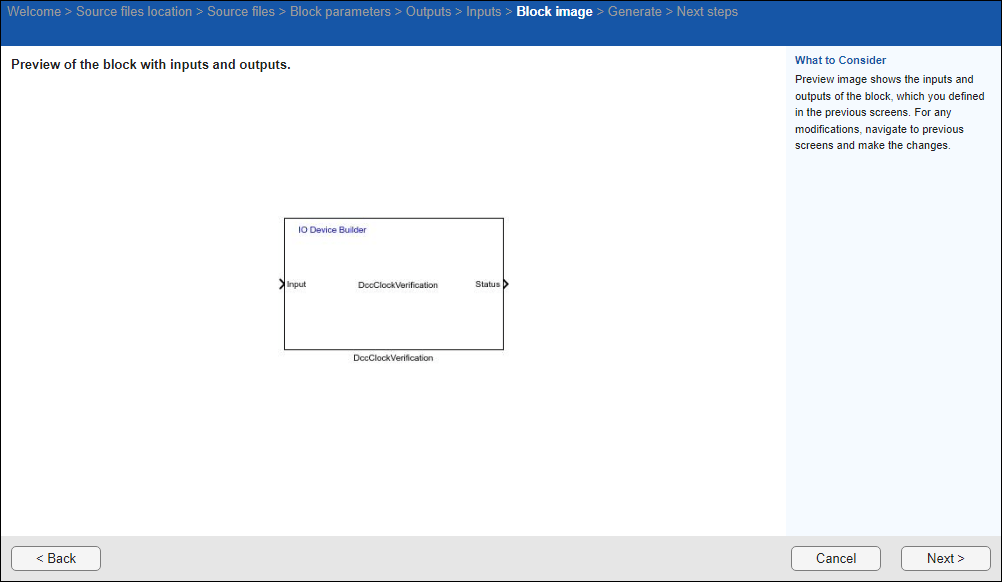
On the Block image page, view the preview of the block with the inputs and outputs you added. Click Next to continue.
Generate System Object Files
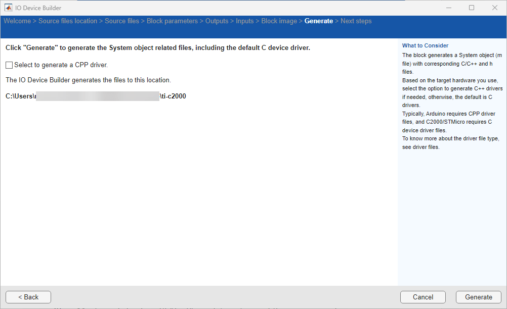
On the Generate page, the file generation location is displayed.
Note: Clear the Select to generate a C++ driver option, as C++ is not supported for TI C2000 boards.
Click Generate to generate the system object files.
Next Steps
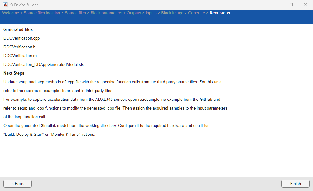
On the Next Steps page, the files generated are shown and the next steps to be performed are displayed. The generate files are created in a directory. This directory also includes a Dependencies folder that contains selected third-party source files. Simply copy these files and the folder to your desired location and integrate them into your Simulink project.
Click Finish to complete the process. The generated 'c' file opens automatically.
Perform these steps.
1. The generated .c file opens automatically. Modify it to include the necessary headers and setup functions by referring to the driver file as required.
A sample generated .c file is shown below.
#include "C:\user\DemoDcc\DccClockVerification.h" //App generated header. Do not modify.
#include "driverlib.h"
#include "device.h"

#define PASS 1
#define FAIL 0

// TestClockFrequency single [1,1] Tunable
// DccErrorTolerance single [1,1] Tunable
// AllowableFrequencyTolerance single [1,1] Tunable
// TestClock uint8 [1,1] Tunable
// DccModuleAddress uint32 [1,1] Non tunable
// ReferenceClock uint8 [1,1] Non tunable
// ReferenceClockFrequency single [1,1] Non tunable

uint32_T  DccModuleAddressParam;
uint8_T  ReferenceClockParam;
float  ReferenceClockFrequencyParam;
void setupFunctionDccClockVerification(float * TestClockFrequency,int size_vector__1,float * DccErrorTolerance,int size_vector__2,float * AllowableFrequencyTolerance,int size_vector__3,
uint8_T * TestClock,int size_vector__4,uint32_T  DccModuleAddress,int size_vector__5,uint8_T  ReferenceClock,int size_vector__6,float  ReferenceClockFrequency,int size_vector__7){

DccModuleAddressParam = DccModuleAddress;
    ReferenceClockParam = ReferenceClock;
    ReferenceClockFrequencyParam = ReferenceClockFrequency;

    if (DccModuleAddressParam == 0) {
        DccModuleAddressParam = DCC0_BASE;
    }
    // Check if DccModuleAddressParam is 1 and set it to DCC1_BASE if it is
    else if (DccModuleAddressParam == 1) {
        DccModuleAddressParam = DCC1_BASE;
    }
}

// Status uint32 [1,1]

void stepFunctionDccClockVerification(uint32_T * Status,int size_vector_1, float * TestClockFrequency,int size_vector__1, float * DccErrorTolerance,int size_vector__2,
float * AllowableFrequencyTolerance,int size_vector__3, uint8_T * TestClock,int size_vector__4){

    bool status=0;
    // Verify the frequency of PLL clock using the XTAL as reference clock
    // FClk1 = PLL frequency = 120MHz
    // FClk0 = XTAL frequency = 20MHz
    // Tolerance = 1%
    // Allowable Frequency Tolerance = 0% (update as per the error in the XTAL frequency)
    // SysClk Freq = 120MHz
    //
    // Note: Update the parameters if you are using different PLL or XTAL frequencies,
    //
    // status = DCC_verifyClockFrequency(DCC0_BASE,
    //                                   DCC_COUNT1SRC_PLL, 120.0F,
    //                                   DCC_COUNT0SRC_XTAL, 20.0F,
    //                                   1.0F, 0.0F, 120.0F);

    status = DCC_verifyClockFrequency(DccModuleAddressParam,
                                      *TestClock, *TestClockFrequency,
                                      ReferenceClockParam, ReferenceClockFrequencyParam,
                                      *DccErrorTolerance, *AllowableFrequencyTolerance, 120.0F);

    //
    // Status of the PLLRAW clock verification
    //
    if (!status)
    {
        *Status = FAIL;
    }
    else
    {
        *Status = PASS;
    }
}
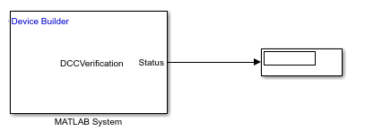
3. In the already opened Simulink model, add a MATLAB System block and assign the generated system object file without .m extension to the block.
4. Add and connect Display blocks to the output ports.
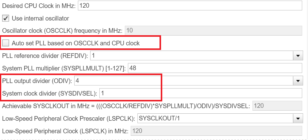
5. Modify the PLL output divider and System clock divider in the Configuration Parameters pane. To achieve a PLL frequency of 120MHz, set these options.
In the Simulink model, navigate to Modeling > Model Settings and in the Configuration Parameters dialog box, click Hardware Implementation > Target hardware resources > Clocking and then modify the PLL output divider and System clock divider as shown in this image.
A sample Simulink model is shown here.
Monitor and Tune the Model
When you perform Monitor and Tune action for the model, the host computer communicates with the target, on which the generated executable runs. To perform Monitor and Tune:
1. In the Simulink model, press Ctrl+E. The Configuration Parameters dialog box appears.
2. Navigate to Code Generation > Optimization and ensure that Tunable is selected for Default parameter behavior.
3. Click Apply and OK.
4. In the Simulink model, click Hardware and click Monitor & Tune.

You can verify the PLLRAW Clock frequency with test clock frequency set to 120MHz.

Other Things to Try
Test the PLLRAW clock with a test clock frequency other than 120 MHz.
Test the PLLRAW clock with a different DCC error tolerance.
Create complex device driver blocks such as LIN, Analog subsystem and so on.