Configuring Timing Parameters for CAN Blocks
The CAN Blocks
The bit rate of these four CAN blocks cannot be set directly:
| C281x CAN Receive |
| C281x CAN Transmit |
| C280x/C28x3x CAN Receive |
| C280x/C28x3x CAN Transmit |
Setting Timing Parameters
Accessing the Timing Parameters
To set the Bitrate for a block whose bitrate cannot be set directly:
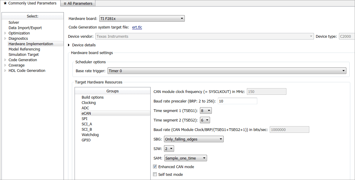
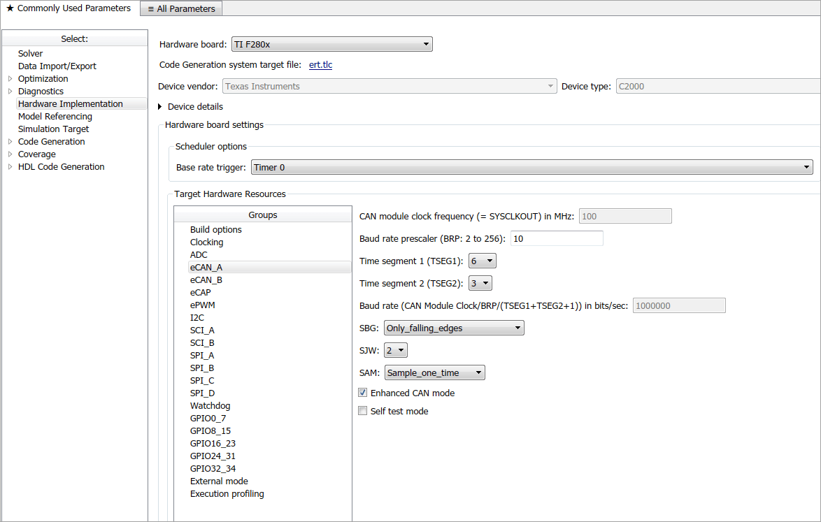
Configure the Target Hardware Resources tab.
Under the Peripherals tab, use the TSEG1, TSEG2, and BaudRatePrescaler (BRP) parameters to set the bitrate.
For example, the Target Hardware Resources tab for the F2812 eZdsp shown in the following figure.

The C280x/C28x3x blocks have two independent CAN modules.

The following sections describe the series of steps and rules that govern the process of setting these timing parameters.
Determining Timing Parameter Values
To determine the values for the timing parameters, complete the following steps:
Determine the CAN Bitrate specification based on your application.
Determine the frequency of the CAN module clock. For example:
CAN module clock = 100 MHz for the F2808 (Same as SYSCLKOUT)
CAN module clock = 150 MHz for the F2812 (Same as SYSCLKOUT)
CAN module clock = 75 MHz for the F28x3x (150 SYSCLKOUT/2)
Estimate the value of the BaudRatePrescaler (BRP).
Solve this equation for BitTime:
BitTime = CAN module clock frequency/(BRP * Bitrate)
Solve this equation for Bitrate:
Bitrate = CAN module clock frequency/(BRP * BitTime)
Estimate values for TSEG1 and TSEG2 that satisfy BitTime = TSEG1 + TSEG2 + 1.
Use the following rules to determine the values of TSEG1 and TSEG2:
where IPT is Information Processing Time, TQ is Time Quanta, and SJW is Synchronization Jump Width, also set in the Target Hardware Resources dialog box.TSEG1 >= TSEG2 IPT (Information Processing Time) = 3/BRP IPT <= TSEG1 <= 16 TQ IPT <= TSEG2 <= 8 TQ 1 TQ <= SJW <= min (4 TQ, TSEG2) Iterate steps 4 through 7 until the values selected for TSEG1, TSEG2, and BRP meet the criteria.
The following illustration shows the relationship between the CAN bit timing parameters.

Working with CAN Bit Timing
Assume that CAN Module Clock Frequency = 75 MHz, and a Bitrate of 1 Mbits/s is required.
Set the BRP to 5. Then substitute the values of CAN Module Clock Frequency, BRP, and Bitrate into the following equation, solving for BitTime:
BitTime = CAN Module Clock Frequency / (BRP * Bitrate)
BitTime = 75e6/(5 *1e6) = 15TQ
Set the values of TSEG1 and TSEG2 to 8TQ and 6TQ respectively. Substitute the values of BitTime from the previous equation, and the chosen values for TSEG1 and TSEG2 into the following equation:
BitTime = TSEG1 + TSEG2 + 1
15TQ = 8TQ + 6TQ + 1
Finally, check the selected values against the rules:
IPT = 3/BRP = 3/10 = .3 IPT <= TSEG1 <= 16 TQ True! .3<=8TQ<=16TQ IPT <= TSEG2 <= 8TQ True! .3 <= 6TQ <= 8TQ 1TQ <= SJW <= min(4TQ, TSEG2) which means that SJW can be set to either 2, 3, or 4 When the chosen values satisfy the criteria, so further iteration is not required.
The following table provides example values for several bit rates when CAN Module Clock Frequency = 75 MHz, as it is with the F28335. Other combinations of the register values are possible.
| Bitrate | TSEG1 | TSEG2 | Bit Time | BRP | SJW |
|---|---|---|---|---|---|
| 0.25 Mbit/s | 8 | 6 | 15 | 20 | 2 |
| 0.5 Mbit/s | 8 | 6 | 15 | 10 | 2 |
| 1 Mbit/s | 8 | 6 | 15 | 5 | 2 |
The following table provides example values for several bit rates when CAN Module Clock Frequency = 100 MHz, as it is with the F2808. Other combinations of the register values are possible.
| Bitrate | TSEG1 | TSEG2 | Bit Time | BRP | SJW |
|---|---|---|---|---|---|
| 0.25 Mbit/s | 6 | 3 | 10 | 40 | 2 |
| 0.5 Mbit/s | 5 | 4 | 10 | 20 | 2 |
| 1 Mbit/s | 6 | 3 | 10 | 10 | 2 |
The following table provides example values for several bit rates when CAN Module Clock Frequency = 150 MHz, as it is with the F2812. Other combinations of the register values are possible.
| Bitrate | TSEG1 | TSEG2 | Bit Time | BRP | SJW |
|---|---|---|---|---|---|
| 0.25 Mbit/s | 8 | 6 | 10 | 40 | 2 |
| 0.5 Mbit/s | 7 | 7 | 10 | 20 | 2 |
| 1 Mbit/s | 8 | 6 | 10 | 10 | 2 |