Main Content

Schedule a Multi-Rate Controller for a Permanent Magnet Synchronous Machine

This example shows how to create a real-time executable for a Texas Instruments™ F28335 embedded target. You will build upon the algorithm specified in the example Field-Oriented Control of Permanent Magnet Synchronous Machine (Embedded Coder) by adding timing and peripheral specifications. You will learn an advanced technique to schedule the algorithm based on the periodic end-of-conversion event of the ADC.

Required hardware:

  • Spectrum Digital® F28335 eZdsp board

  • Digital Motor Controller board: Spectrum Digital DM550

  • Three-phase Permanent Magnet Synchronous Motor with quadrature encoder

Note: Match the characteristics of the power supply and the amplifier with the input characteristics of the selected motor.

Introduction

The goal is to create a real-time executable for a Spectrum Digital F28335 eZdsp and schedule the controller execution using an ADC end-of-conversion interrupt. This goal is achieved using an advanced technique where the controller and peripherals are scheduled by a periodic ADC end-of-conversion interrupt.

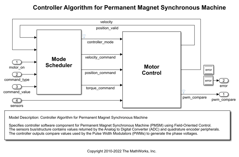
This example builds upon the controller algorithm specified in the example Field-Oriented Control of Permanent Magnet Synchronous Machine (Embedded Coder). Refer to that example to explore how the controller algorithm behaves during system simulation with a model of a Permanent Magnet Synchronous Machine.

Configure the Controller Model for the TI F28335 Processor

To facilitate transitioning between simulation and code generation phases of a design, the controller algorithm is specified in its own c28335_pmsmfoc model. The controller algorithm is introduced in the example Field-Oriented Control of Permanent Magnet Synchronous Machine (Embedded Coder). In this example the controller model is configured for the TI F28335 target hardware. An archived library allowing incremental build will be automatically generated for the controller model.

Schedule Controller using ADC End-of-Conversion Interrupt

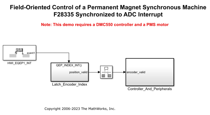
In this section, the c28335_pmsmfoc_adcinterrupt model is used to call the controller model using a Model Block configured to c28335_pmsmfoc. Within the Controller_And_Peripherals subsystem, the ePWM1 block is configured to trigger the ADC conversion so that sampling does not occur during a PWM edge transition (thus minimizing noise on the sampled signals). The controller is scheduled using the ADC end-of-conversion interrupt. This provides the shortest and most deterministic delay between the ADC conversion and the new values of PWM duty cycles.

By default, a model set for a processor such as TI F28335 will use a hardware timer to schedule all synchronous rates present in the model. If we keep this default behavior, the controller algorithm will not be synchronized with the ADC which could introduce latencies or drifts between the controller algorithm and the ADC conversions. In the c28335_pmsmfoc_adcinterrupt Model Configuration Parameters, under Hardware Implementation > Scheduler options, ADCINT1 is selected for the Scheduler interrupt source. This option replaces the default scheduler interrupt source set to CPU Timer 0 interrupt with the ADC Interrupt coming from ADC module 1 (ADCINT1). On the ADC block, an end-of-conversion interrupt is enabled for ADC module 1. Since the ADC conversions are launched from the PWM module running at 25kHz, and since the base rate (fundamental sample time) of the model is set to 40us, it is safe to replace the scheduler interrupt source with the ADC interrupt triggering periodically at 40us. While using the default CPU Timer 0 as a scheduler interrupt source, the tool will automatically set the CPU Timer 0 to honor the base rate of the model. While replacing the scheduler interrupt source with ADCINT1, like in this example, it is the responsibility of the user to ensure that ADCINT1 will trigger periodically at the base rate used in the model.

This model showed an advanced technique for scheduling a multi-rate controller algorithm using an ADC end-of-conversion interrupt. This technique is valid for this example because we have configured the model to generate the ADC end-of-conversion interrupt at the same periodic rate as the sample time specified in the controller algorithm. If you do not ensure this sampling consistency, the behavior of generated code will be different than that of simulation.

Conclusion

This example showed how to create a real-time executable for a Texas Instruments F28335 embedded target using an advanced scheduling technique triggering the controller algorithm based on an ADC end-of-conversion interrupt. In this technique, the hardware is configured to generate a periodic interrupt with the same rate as the fastest rate specified in the controller.

More About

C28x eQEP