Line Buffer
Store video lines and return neighborhood pixels
Libraries:
Vision HDL Toolbox /
Utilities
Description
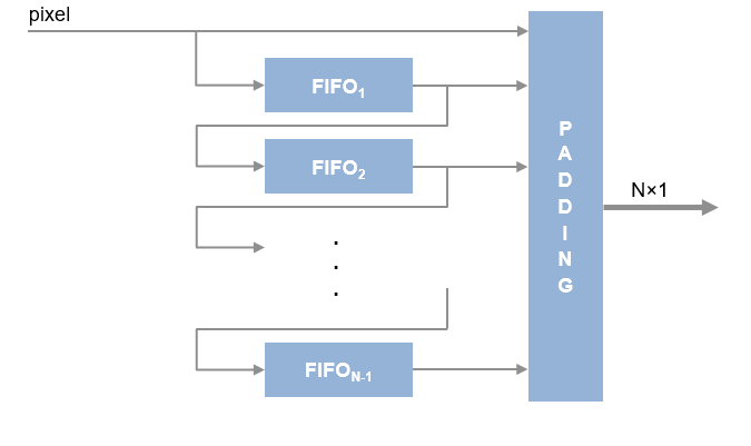
The Line Buffer block selects neighborhood pixels from streaming image data. It handles video control signals and edge padding, and is pipelined for high-speed video designs. The block outputs one column of the neighborhood at a time, as a H-by-M matrix, where H is the vertical size of the neighborhood and M is the number of input pixels per cycle, usually 1. To compose a neighborhood for further processing, use the shiftEnable signal to store the output columns, including padding, in a shift register. This block allows you to share the line buffer resources when your design performs multiple operations on the same neighborhood.
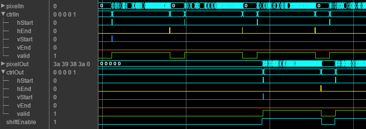
The following waveform shows the Line
Buffer block returning 5-by-1 pixel columns that make up a 5-by-5
neighborhood. The time frame shown is at the beginning (top-left corner) of an input
frame. The output starts after the block has stored two
(floor(H/2)) lines and is receiving the
start of the third line. The shiftEnable signal is asserted two
cycles earlier than the output ctrl.valid
signal, which indicates that the first two
(floor(H/2)) columns are exclusively padding
pixels. Similarly, shiftEnable stays high for two extra cycles at
the end of the line.
Examples
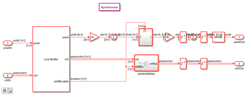
Construct a Filter Using Line Buffer
Use the Line Buffer block to extract neighborhoods from an image for further processing. The model constructs a separable Gaussian filter.
Filter Multipixel Video Streams
Design filters that operate on a multipixel input video stream. Use multipixel streaming to process high-resolution or high-frame-rate video with the same synthesized clock frequency as a single-pixel streaming interface. Multipixel streaming also improves simulation speed and throughput because fewer iterations are required to process each frame, while maintaining the hardware benefits of a streaming interface.

Increase Throughput by Omitting Padding
Reduce latency and save hardware resources by not adding padding pixels at the edge of each frame.
Ports
This block uses a streaming pixel interface with a bus for
frame control signals. This interface enables the block to operate independently of image size
and format. The pixel ports on this block support single pixel streaming or
multipixel streaming. Single pixel streaming accepts and returns a single pixel value each clock
cycle. Multipixel streaming accepts and returns a vector of M pixels per
clock cycle to support high-frame-rate or high-resolution formats. The M
value corresponds to the Number of pixels parameter of the Frame
To Pixels block. Along with the pixel, the block accepts and returns a
pixelcontrol bus that contains five control signals. The control signals
indicate the validity of each pixel and their location in the frame. For multipixel streaming,
one set of control signals applies to all pixels in the vector. To convert a frame (pixel
matrix) into a serial pixel stream and control signals, use the Frame
To Pixels block. For a full description of the interface, see Streaming Pixel Interface.
Input
Output
Parameters
Tips
When you use this block inside an Enabled Subsystem (Simulink), the enable signal pattern must maintain the timing of the pixel stream, including the minimum blanking intervals. If the enable pattern corrupts the timing of the pixel stream, you might see partial output frames, corrupted pixel stream control signals, or mismatches between Simulink® and HDL simulation results. You may need to extend the blanking intervals to accommodate for cycles when the enable is low. For more information, see Configure Blanking Intervals.
Algorithms
The block stores H – 1 lines of valid pixels, as specified by the
neighborhood size. It adds padding bits at the edge of the frame. The block returns the
first output column once it can form a complete neighborhood column, which occurs at the
start of input line floor(H/2).