在部署的 Simulink 模型上执行 XCP 操作
此示例说明如何使用 XCP 协议功能从部署到 Windows® 可执行文件的 Simulink® 模型执行基本 XCP 操作。该示例基于 TCP 协议执行 XCP 操作,包括使用直接内存访问修改模型的特征参数,以及使用直接内存访问和动态 DAQ 列表读取模型的测量变量参数。
XCP 是一种高级协议,用于访问和修改模型、算法或 ECU 的内部参数和变量。有关详细信息,请参阅 ASAM 标准。
算法概述
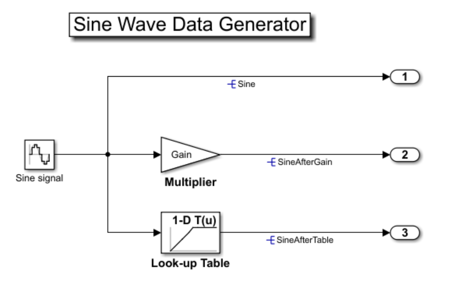
此示例中使用的算法是构建并部署为 XCP 服务器的 Simulink 模型。模型已编译,可在文件 XCPServerSineWaveGenerator.exe 中运行。此外,A2L 文件 XCPServerSineWaveGenerator.a2l 是作为该编译过程的输出提供的。该模型包含三个测量变量和两个特征变量,均可通过 XCP 访问。由于模型已部署,因此不需要 Simulink 来运行此示例。下图展示了该模型。
运行 XCP 服务器模型
要与 XCP 服务器通信,必须运行部署的模型。通过使用 system 函数,您可以从 MATLAB® 内部执行 XCPServerSineWaveGenerator.exe。该函数需要构造一个指向可执行文件的参量列表。将打开一个单独的命令行窗口,显示服务器正在运行的输出。输入 pwd 获得当前工作目录。
sysCommand = ['"', fullfile(pwd, 'XCPServerSineWaveGenerator.exe'),'"', ' &'];
system(sysCommand);
打开 A2L 文件
使用 xcpA2L 函数打开说明服务器模型的 A2L 文件。
a2lInfo = xcpA2L("XCPServerSineWaveGenerator.a2l");TCP 是用于与 XCP 服务器通信的传输协议。TCP 连接的详细信息,如 IP 地址和端口号,包含在 TransportLayerTCPInfo 属性中。
a2lInfo.TransportLayerTCPInfo
ans =
  XCPonIP with properties:
          CommonParameters: [1×1 xcp.a2l.CommonParameters]
    TransportLayerInstance: ''
                      Port: 17725
                   Address: 2.1307e+09
             AddressString: '127.0.0.1'
创建 XCP 通道
要创建到服务器的活动 XCP 连接,请使用 xcpChannel 函数。该函数需要引用服务器 A2L 文件以及用于与服务器进行报文传输的传输协议类型(在此示例中仅为 TCP)。
xcpCh = xcpChannel(a2lInfo, "TCP")xcpCh =
Channel with properties:
ServerName: 'ModuleName'
A2LFileName: 'XCPServerSineWaveGenerator.a2l'
TransportLayer: 'TCP'
TransportLayerDevice: [1×1 struct]
SeedKeyDLL: []
连接到服务器
要激活与服务器的通信,请使用 connect 函数。
connect(xcpCh)
直接采集读取 XCP 测量变量值
本节说明如何使用函数 readMeasurement 读取模型的测量变量参数,以便对模型服务器进行直接内存访问。
直接采集测量数据
readMeasurement 函数从服务器采集给定测量变量的当前值。
readMeasurement(xcpCh, "Sine") ans = 0
readMeasurement(xcpCh, "SineAfterGain")ans = -1.9021
readMeasurement(xcpCh, "SineAfterTable")ans = -0.9511
使用动态 DAQ 列表读取 XCP 测量变量
除了通过直接内存访问获取数据,另一种读取测量数据的方法是使用动态 DAQ 列表。本节说明如何使用动态 DAQ 列表读取模型的测量变量参数。
创建和查看测量变量列表
使用 createMeasurementList 函数创建动态 DAQ 列表。
createMeasurementList(xcpCh, "DAQ", "100 ms", ["Sine", "SineAfterGain", "SineAfterTable"])
从 XCP 服务器采集数据
使用 startMeasurement 函数启动已配置的动态 DAQ 列表。运行几秒后,使用 stopMeasurement 函数停止测量。
startMeasurement(xcpCh)
pause(3);
stopMeasurement(xcpCh)
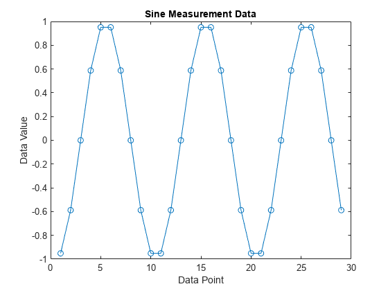
检索 Sine 测量变量数据
要检索从 XCP 通道采集的 Sine 测量变量的数据,请使用 readDAQ 函数。
dataSine = readDAQ(xcpCh, "Sine");
plot(dataSine, "o-")
title("Sine Measurement Data")
xlabel("Data Point")
ylabel("Data Value")
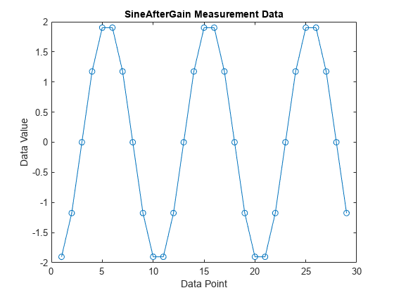
检索 SineAfterGain 测量变量的数据
要检索从 XCP 通道采集的 SineAfterGain 测量变量的数据,请使用 readDAQ 函数。
dataSineAfterGain = readDAQ(xcpCh, "SineAfterGain");
plot(dataSineAfterGain, "o-")
title("SineAfterGain Measurement Data")
xlabel("Data Point")
ylabel("Data Value")
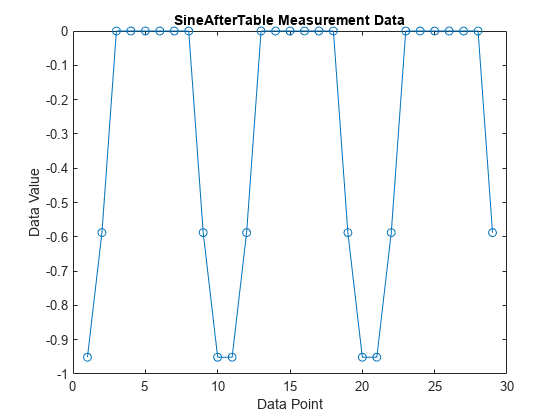
检索 SineAfterTable 测量变量的数据
要检索从 XCP 通道采集的 SineAfterTable 测量变量的数据,请使用 readDAQ 函数。
dataSineAfterTable = readDAQ(xcpCh, "SineAfterTable");
plot(dataSineAfterTable, "o-")
title("SineAfterTable Measurement Data")
xlabel("Data Point")
ylabel("Data Value")
释放测量变量列表
使用 freeMeasurementLists 函数释放测量变量列表。
freeMeasurementLists(xcpCh);
标定 XCP 特征变量
本节说明如何使用直接内存访问来标定模型的测量变量参数。请注意,本节中使用两个参数,其中 Gain 是乘数,ydata 指定一维查找表的输出数据点。
检查预加载的特征变量值
使用 readCharacteristic 函数读取特征变量 Gain 的当前值。
initialGain = readCharacteristic(xcpCh, "Gain")initialGain = 2
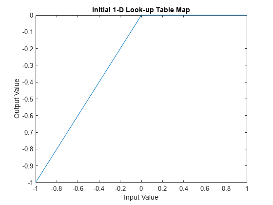
使用 readAxis 和 readCharacteristic 读取当前一维查找表特征变量,然后绘制映射图。此表实际上将任何正输入值映射到零输出。
inputBreakpoints = readAxis(xcpCh, "xdata")inputBreakpoints = 1×7
-1.0000 -0.5000 -0.2000 0 0.2000 0.5000 1.0000
outputPoints = readCharacteristic(xcpCh, "ydata")outputPoints = 1×7
-1.0000 -0.5000 -0.2000 0 0 0 0
plot(inputBreakpoints, outputPoints);
title("Initial 1-D Look-up Table Map");
xlabel("Input Value");
ylabel("Output Value");
创建测量变量列表
此示例探讨了原始的和经两个特征变量修改的测量变量 Sine 的值。要可视化标定前后 Sine 的连续变化值,请使用 DAQ 列表采集测量数据值。使用 createMeasurementList 函数创建一个 DAQ 列表,其中包含所有服务器基于 Sine 的可用测量变量。
createMeasurementList(xcpCh, "DAQ", "100 ms", ["Sine", "SineAfterGain", "SineAfterTable"])
标定前获取测量变量值
使用 startMeasurement 函数和 stopMeasurement 函数短时间运行 DAQ 列表。
startMeasurement(xcpCh);
pause(3);
stopMeasurement(xcpCh);
要检索 DAQ 列表采集的所有 Sine 相关测量变量数据,请使用 readDAQ 函数。基于 100 毫秒的事件,3 秒内检索的采样数预计为 30 个,但由于 XCP 服务器运行在非实时操作系统的 Windows 上,因此根据操作系统的占用情况,实际检索的采样数可能少于 30 个。
sine = readDAQ(xcpCh, "Sine");
sineAfterGain = readDAQ(xcpCh, "SineAfterGain");
sineAfterTable = readDAQ(xcpCh, "SineAfterTable");
标定前检查测量变量值
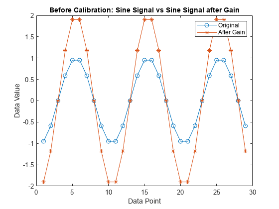
绘制 SineAfterGain 测量变量的值对基本 Sine 测量变量的值的图。Gain 后的值增至原始测量变量的值的 2 倍,因为特征变量 Gain 的预加载值为 2,如前所示。
plot(sine, "o-"); hold on;
plot(sineAfterGain, "*-"); hold off;
title("Before Calibration: Sine Signal vs Sine Signal after Gain");
legend("Original", "After Gain");
xlabel("Data Point");
ylabel("Data Value");
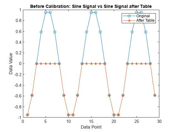
绘制 SineAfterTable 测量变量的值对基本 Sine 测量变量的值的图。根据预加载的一维查找表,原始测量变量的值的任何正值都映射到零,因此修改后的信号看起来像是被截断的并且没有任何正值。
plot(sine, "o-"); hold on;
plot(sineAfterTable, "*-"); hold off;
title("Before Calibration: Sine Signal vs Sine Signal after Table");
legend("Original", "After Table");
xlabel("Data Point");
ylabel("Data Value");
标定增益和一维查找表
使用 writeCharacteristic 将新值写入特征变量 Gain,并使用 readCharacteristic 执行读取以验证更改。
writeCharacteristic(xcpCh, "Gain", 0.5);
newGain = readCharacteristic(xcpCh, "Gain")
newGain = 0.5000
使用 writeCharacteristic 将新数据点写入一维查找表的输出。
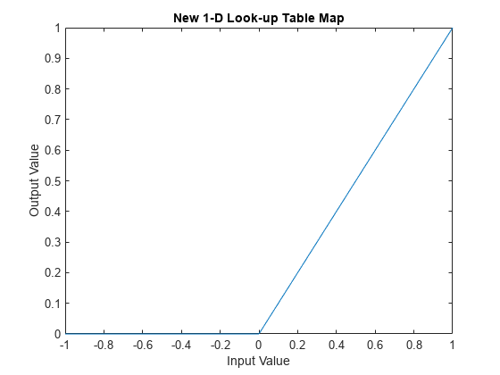
writeCharacteristic(xcpCh, "ydata", [0 0 0 0 0.2 0.5 1]);使用 readAxis 和 readCharacteristic 读取新一维查找表数据,然后绘制映射。现在,该表实际上将所有负输入值均映射到零输出。
inputBreakpoints = readAxis(xcpCh, "xdata")inputBreakpoints = 1×7
-1.0000 -0.5000 -0.2000 0 0.2000 0.5000 1.0000
newOutputPoints = readCharacteristic(xcpCh, "ydata")newOutputPoints = 1×7
0 0 0 0 0.2000 0.5000 1.0000
plot(inputBreakpoints, newOutputPoints);
title("New 1-D Look-up Table Map");
xlabel("Input Value");
ylabel("Output Value");
标定后获得测量变量值
使用 startMeasurement 函数和 stopMeasurement 函数短时间运行 DAQ 列表。
startMeasurement(xcpCh);
pause(3);
stopMeasurement(xcpCh);
要检索 DAQ 列表采集的所有 Sine 相关测量变量数据,请使用 readDAQ 函数。
sine = readDAQ(xcpCh, "Sine");
sineAfterGain = readDAQ(xcpCh, "SineAfterGain");
sineAfterTable = readDAQ(xcpCh, "SineAfterTable");
标定后检查测量变量值
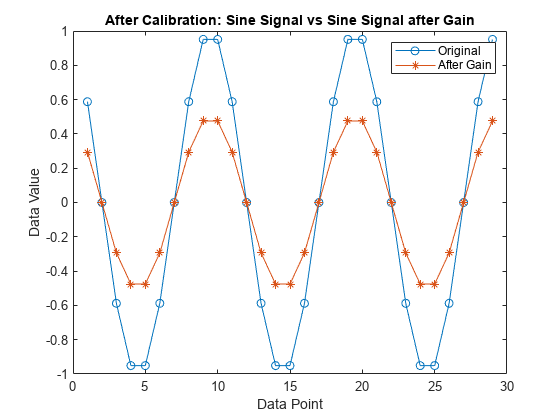
绘制 SineAfterGain 测量变量的值对基本 Sine 测量变量的值的图。现在 Gain 后的值降至原始测量变量值的二分之一,因为标定后特征变量 Gain 的值设置为 0.5。
plot(sine, "o-"); hold on;
plot(sineAfterGain, "*-"); hold off;
title("After Calibration: Sine Signal vs Sine Signal after Gain");
legend("Original", "After Gain");
xlabel("Data Point");
ylabel("Data Value");
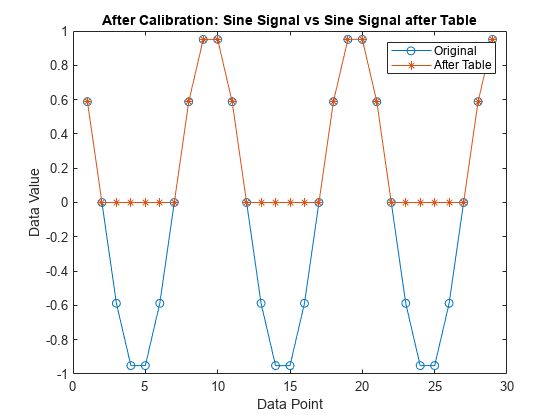
绘制 SineAfterTable 测量变量的值对基本 Sine 测量变量的值的图。根据新的一维查找表,原始测量变量的所有负值都映射到零,因此修改后的信号看起来是以不同方式截断的,并且没有任何负值。
plot(sine, "o-"); hold on;
plot(sineAfterTable, "*-"); hold off;
title("After Calibration: Sine Signal vs Sine Signal after Table");
legend("Original", "After Table");
xlabel("Data Point");
ylabel("Data Value");
断开与服务器的连接
要使与服务器的通信处于非活动状态,请使用 disconnect 函数。
disconnect(xcpCh)
清理
clear a2lInfo