HDL Code Generation Support
You can use Simulink® for rapid prototyping of hardware designs. Wireless HDL Toolbox™ blocks, when used with HDL Coder™, support HDL code generation. HDL Coder tools generate target-independent synthesizable Verilog® and VHDL® code for FPGA programming or ASIC prototyping and design.
HDL Code Generation Support in Wireless HDL Toolbox
Most blocks in Wireless HDL Toolbox support HDL code generation.
The following blocks are for simulation only and are not supported for HDL code generation:
Frame To Samples
Samples To Frame
FIL Frame To Samples
FIL Samples To Frame
Other Blocks Supporting HDL Code Generation
Other MathWorks® products also include blocks supported for HDL code generation that you can use to build up your design.
To create a library of HDL-supported blocks from all your installed products, enter hdllib (HDL Coder) at the MATLAB® command line. This command requires an HDL Coder license.
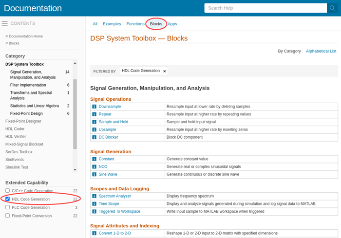
You can also view blocks that are supported for HDL code generation in documentation by filtering the block reference list. Click Blocks in the blue bar at the top of the Help window, then select the HDL code generation check box at the bottom of the left column. The blocks are listed in their respective products. You can use the table of contents in the left column to navigate between products and categories.
Refer to the "Extended Capabilities > HDL Code Generation" section of each block page for block implementations, properties, and restrictions for HDL code generation.
Streaming Sample Interface in HDL
The streaming sample control bus data type used by Wireless HDL Toolbox blocks is flattened into separate signals in HDL.
In VHDL, the interface is declared as:
  PORT( clk             :   IN    std_logic;
        reset           :   IN    std_logic;
        enb             :   IN    std_logic;
        in0             :   IN    std_logic_vector(7 DOWNTO 0); -- uint8
        in1_start       :   IN    std_logic;
        in1_end         :   IN    std_logic;
        in1_valid       :   IN    std_logic;
        out0            :   OUT   std_logic_vector(7 DOWNTO 0); -- uint8
        out1_start      :   OUT   std_logic;
        out1_end        :   OUT   std_logic;
        out1_valid      :   OUT   std_logic
        );
In Verilog, the interface is declared as:
  input   clk;
  input   reset;
  input   enb;
  input   [7:0] in0;  // uint8
  input   in1_start;
  input   in1_end;
  input   in1_valid;
  output  [7:0] out0;  // uint8
  output  out1_start;
  output  out1_end;
  output  out1_valid;