LTE HDL SIB1 Recovery
This example shows how to design an HDL optimized receiver that can recover the first System Information Block (SIB1) from an LTE downlink signal.
Introduction
This design builds on the LTE HDL MIB Recovery, adding the processing required to decode SIB1. It is based on the LTE Toolbox™ Cell Search, MIB and SIB1 Recovery (LTE Toolbox).
In order to decode the SIB1 message, additional steps are required after the MIB (Master Information Block) has been decoded. This design adds functionality to locate and decode the PCFICH (Physical Control Format Indicator Channel), the PDCCH (Physical Downlink Control Channel), and the PDSCH (Physical Downlink Shared Channel). The extensible architecture used in the LTE HDL MIB Recovery allows the design to be expanded, while reusing the core functionality of the MIB recovery implementation. This design can be implemented on SoC platforms using hardware-software co-design and hardware support packages. See Deploy LTE HDL Reference Applications on FPGAs and SoCs.
Summary of SIB1 Processing Stages
The initial stages of SIB1 recovery are the same as for the LTE HDL MIB Recovery, composed of the cell search, PSS/SSS detection, OFDM demodulation, and MIB decoding. LTE signal detection, timing and frequency synchronization, and OFDM demodulation are performed on the received data, providing information on the subframe number, duplex mode, and cell ID of the received waveform. The received data is buffered into the grid subframe memory buffer and, once a complete subframe has been stored in the memory, the channel estimate is calculated. The channel estimate can then be used to equalize the grid as data is read out from the buffer. When subframe 0 has been stored in the buffer, and the channel estimate calculated, the Physical Broadcast Channel (PBCH) can then be retrieved from the grid, equalized, and decoded, recovering the MIB message.
The MIB message contains a number of parameters which are required to decode the subsequent channels. One of these parameters is the System Frame Number (SFN). The SFN is required to determine the location of the SIB1 message, since the SIB1 message is only sent in even numbered frames (mod(SFN,2) = 0). Hence, if the MIB message was decoded within an odd frame, the receiver must wait until the next even frame before attempting to decode the SIB1. When the receiver has decoded the MIB message, and has received subframe 5 of an even frame, an attempt at decoding the SIB1 can be made.
The MIB message also provides the NDLRB system parameter, indicating the Number of Downlink Resource Blocks used by the transmitter. For different NDLRB values (different bandwidths) the number of active subcarriers is different. Hence the NDLRB affects the indexing of the resource grid memory for each of the channels processed after the PBCH.
NDLRB is first used to calculate the Resource Elements (REs) allocated to the Physical Control Format Indicator Channel (PCFICH), and the corresponding symbols can be retrieved from the resource grid. The PCFICH Decoder then attempts to decode the CFI data using the symbols retrieved from the resource grid.
The CFI indicates the number of OFDM symbols allocated to the Physical Downlink Control Channel (PDCCH). The CFI, in conjunction with the MIB parameters NDLRB, PHICH Duration, and Ng, is used to calculate which Resource Elements (REs) are allocated to the PDCCH. These REs are requested from the grid, and passed to the PDCCH decoder. If the signal being decoded is using Time Division Duplexing (TDD) the PDCCH allocation varies based on the TDD configuration used. Because the TDD configuration is not know at this point, each of the TDD configurations that affect the PDCCH allocation are tried, until successfully decoding.
Once the PDCCH has been decoded, a blind search of the PDCCH common search space is conducted to find the DCI (Downlink Control Information) message for the SIB1. This DCI message has a CRC scrambled with the SI-RNTI (System Information Radio Network Temporary Identifier) and carries information about the allocation and encoding of the SIB1 message within the PDSCH. The search operation blindly attempts to decode DCI messages with a number of possible formats, from a number of candidates. If the signal being decoded is using TDD and a DCI message is not found during the search, then PDCCH decoding will be re-attempted for any untried TDD configurations.
Once located, the DCI message is parsed, giving the DCI allocation type, RIV, and Gap parameters required for the PDSCH resource allocation calculation. The Physical Resource Blocks (PRBs) allocated to the SIB1 message within the PDSCH can then be calculated. Parsing the DCI message also provides information on the transport block length and redundancy versions required to decode the PDSCH.
Using the PRB allocation information the REs allocated to the SIB1 message within the PDSCH can be calculated. The PDSCH decoding then processes the data retrieved from the resource grid. If decoding is error free the SIB1 message bits are returned.
Architecture and Configuration
The architecture is designed to be extensible, allowing channel processing subsystems to be added, removed, or exchanged for alternative implementations. This extensibility is illustrated by the additions made to the MIB design to produce the SIB1 design. The core functionality is the same, with additional processing and control added for the three extra channels required to decode the SIB1.

To allow reuse and sharing of the main subsystems of the model, the example uses Model References. Model referencing allows for unit testing of each of the subsystems, and for the models to be instantiated in multiple different examples. The LTE HDL Cell Search, LTE HDL MIB Recovery and LTE HDL SIB1 recovery all share reference models.
Cell search, synchronization and OFDM demodulation perform initial stages of detecting a downlink signal and synchronization. Unequalized grid data is streamed out to be buffered in the grid memory for further processing.
The central resources of the grid memory, channel estimation, and channel equalization are grouped together, with an interface such that data can be requested by providing an address to the grid, and equalized symbols are output for processing by the decoding stages.
The indexing subsystems request data from the grid by providing a subcarrier number, an OFDM symbol number, and a read enable flag. These signals are grouped together in a bus for easier routing in the Simulink model. Only one indexing subsystem can access the grid at a time. A controller is used to avoid contention and enable the indexing subsystems at the correct time. Each of the indexing subsystems has a corresponding decoding subsystem, which attempts to decode the data requested from the grid by the indexing subsystem.
The decoding subsystems receive equalized complex symbols from the grid, with a signal indicating when the incoming data is valid. The decoding subsystems must be enabled before they will start to process valid samples at the input, and it is expected that only one of the decoding subsystems will be enabled at any point in time. A central controller for the SIB1 decoder enables the decoding subsystems at the appropriate time.
The control subsystem tracks the state of the decoder and enables the decoding and indexing subsystems in the correct sequence using the done, valid, detected, and error signals (as appropriate) for the various processing stages.
The DCI resource allocation function (ltehdlDCIResourceAllocation) was selected for implementation on software, as part of a hardware/software co-design implementation. This function was selected due to the low frequency of calculation, and the complex loop behavior making it inefficient to implement in hardware.
Structure of Example Model
The top-level of the ltehdlSIB1Recovery model is shown in the figure below. The HDL LTE SIB1 subsystem supports HDL code generation. The SW DCI Resource Allocation subsystem represents the software portion of a design partitioned for hardware/software co-design implementation. The stateViewer MATLAB Function block generates text information messages based on the decoderState signal from the HDL LTE SIB1, and prints this information to both the Simulink Diagnostic Viewer and to a MATLAB figure window. The stateViewer also produces the stopSimulation signal, which stops the simulation when the decoder reaches a terminal state, as indicated by the text information messages.
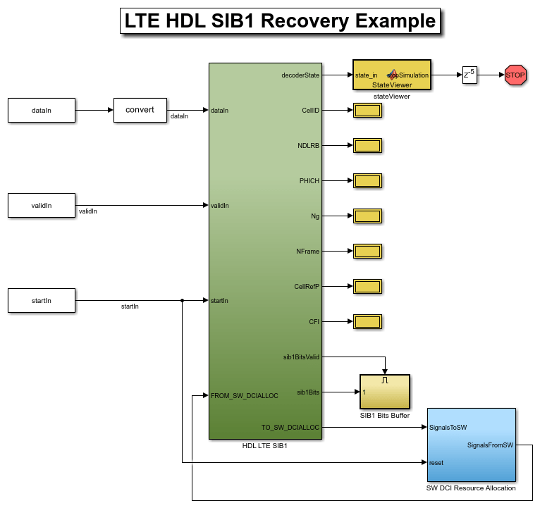
SW DCI Resource Allocation
The SW DCI Resource Allocation subsystem contains an instance of the ltehdlDCIResourceAllocation model. Buses are used here to facilitate signal routing to and from this subsystem.

dciRecourceAllocation
The ltehdlDCIResourceAllocation model reference performs parsing of the DCI message bits, generates the DCI parameters, then uses the DCI parameters to perform the DCI Physical Resource Block (PRB) allocation calculation. These operations are equivalent to the LTE Toolbox functions lteDCI and lteDCIResourceAllocation. Due to the complexity of the PRB allocation calculation, this part of the design was selected for implementation in software, as an HDL implementation would require a large amount of hardware resources.

HDL LTE SIB1
The HDL LTE SIB1 subsystem contains 2 subsystems. The Downlink Sync Demod subsystem is an instance of the ltehdlDownlinkSyncDemod model, which is described in the LTE HDL Cell Search example. It performs the cell search, timing and frequency synchronization, and OFDM demodulation. The HDL MIB + SIB1 Decoder subsystem performs the channel decoding operations required to decode the MIB and SIB1 messages, as described below.
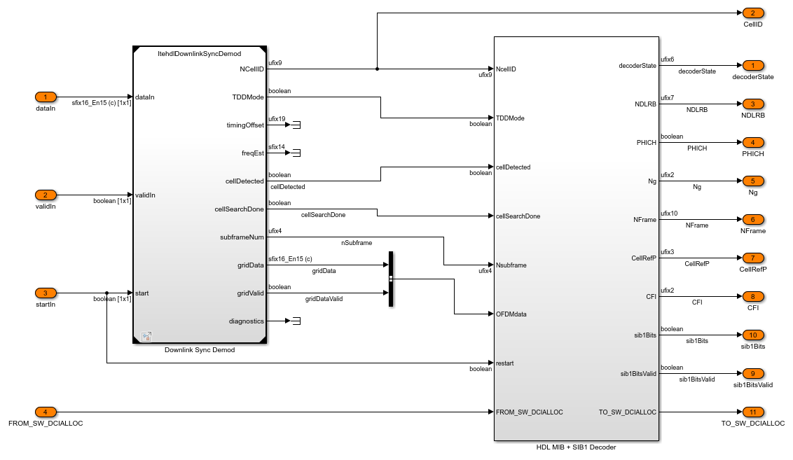
HDL MIB + SIB1 Decoder
The HDL MIB + SIB1 Decoder structure can be seen below. It receives OFDM demodulated grid data from the Downlink Sync Demod subsystem, and stores the data in a subframe buffer, Resource Grid Memory. It then calculates the channel estimate for the received data in the Channel Estimation subsystem and uses this to equalize data as it is read out of the Resource Grid Memory. A series of channel decoding steps are then performed in order to decode the SIB1 message. In total there are 10 referenced models at this level of hierarchy: 4 channel decoders, 4 channel index generation subsystems, and 2 subsystems performing resource grid buffering, channel estimation, and equalization.
The PBCH Indexing, Resource Grid Memory, Channel Equalization and MIB Decoder all instantiate the same referenced models used in the MIB example. For more detailed information about the operation of these referenced models, refer to LTE HDL MIB Recovery.
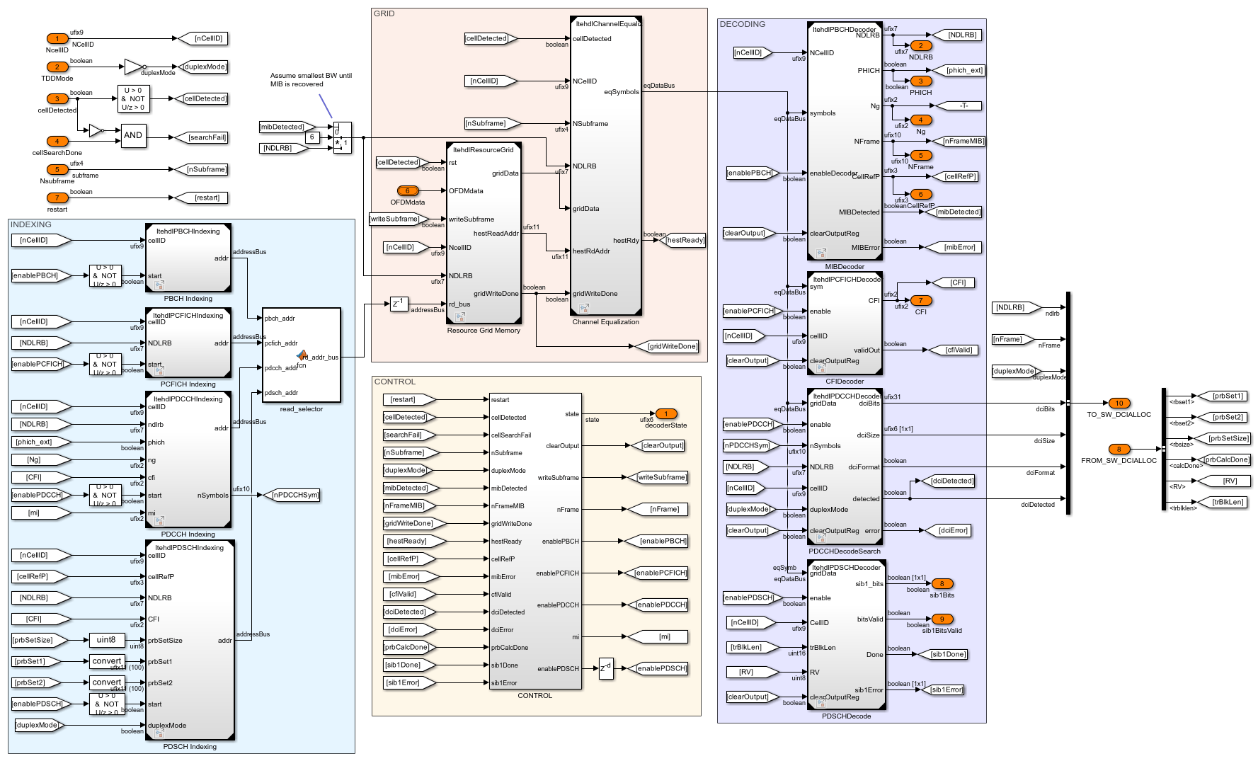
Indexing Subsystems
There are 4 indexing subsystems, corresponding to the 4 channels that need to be decoded in order to receive a SIB1 message: PBCH, PCFICH, PDCCH, and PDSCH. Each of the indexing subsystems has a corresponding decoding subsystem. The indexing subsystems use an address bus, consisting of a read address corresponding to the subcarrier number, a read bank corresponding to an OFDM symbol, and a read enable signal to control access to the grid. The read_selector MATLAB Function block selects between the outputs of the 4 indexing subsystems based on the read enable signal. It is assumed that only one indexing subsystem will attempt to read from the grid at any point in time, with the CONTROL subsystem in charge of enabling the indexing subsystems at the appropriate time.
PBCH Indexing
The PBCH Indexing block references the ltehdlPBCHIndexing model. It performs the index generation for the PBCH and is equivalent to the LTE Toolbox function ltePBCHIndices.

PCFICH Indexing
The PCFICH Indexing block references the ltehdlPCFICHIndexing model. It generates the indices required to read the PCFICH symbols from the grid memory and is equivalent to the LTE Toolbox function ltePCFICHIndices. The PCFICH is always in the first OFDM symbol (the first memory bank of the grid buffer) and is 16 symbols in length, in 4 groups of 4 symbols. The 4 groups of symbols are distributed at quarters of the occupied bandwidth, with an offset dependent on the Cell ID.
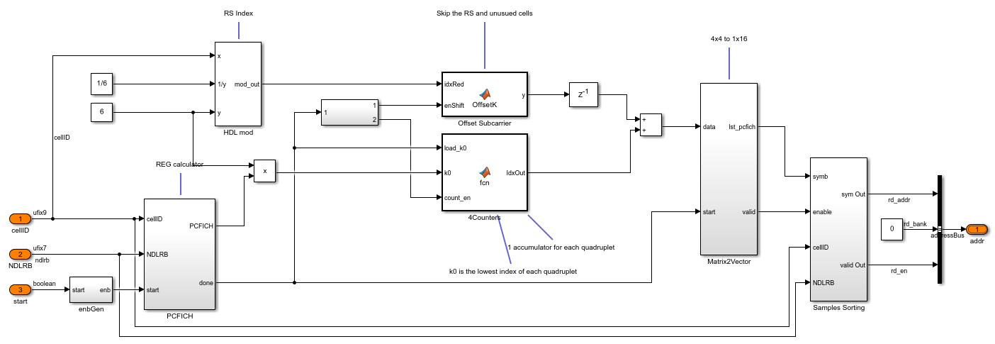
PDCCH Indexing
The PDCCH Indexing subsystem generates the indices required to read the PDCCH symbols from the grid memory. It references the ltehdlPDCCHIndexing model and is equivalent to the LTE Toolbox functions ltePDCCHIndices and ltePDCCHDeinterleave. The PDCCH spans between 1 and 4 OFDM symbols, as defined by the value decoded from the PCFICH. The number of subcarriers spanned by the PDCCH depends on NDLRB. As a result, the number of symbols read from the grid varies, which is indicated by the nSymbols output. The PDCCH occupies all of the OFDM symbols indicated by the CFI, but must exclude any locations which have already been allocated to other channels, such as the PCFICH and PHICH. The main indexing calculation is performed by the PDCCH_Index_Gen subsystem. It calculates the locations of the PCFICH and PHICH then excludes these locations from the range of indices occupied by the PDCCH. In TDD mode number of symbols occupied by the PHICH varies based on the TDD configuration. For different TDD configurations there are three possible values of mi (0, 1, and 2), as specified in section 6.9 of [ 1 ], which is a multiplier to the size of the region allocated to the PHICH. When in the duplexing mode is FDD, mi is always 1. The size of the PDCCH in terms of both quadruplets (groups of 4 symbols) and symbols is given by the Mquad and Msymb outputs.
The ramAddrCalc and lk_ram subsystems are used to perform a cyclic shift on the quadruplets using the cellID. Because the DCI message for SIB1 is always transmitted in the common search space of the PDCCH, it is possible to reduce the number of symbols that are read from the grid memory by retrieving only the symbols from the common search space. In order to do this the PDCCH deinterleaving operation is performed, and the first 576 symbols are requested from the grid. If there are less than 576 symbols in the PDCCH then all of the symbols will be requested. In LTE Toolbox, the PDCCH deinterleaving operation is performed as part of the ltePDCCHDecode function. However, as this function simply re-orders the data and does not change the data content, it is possible to move this processing stage to an earlier point in the receiver. By moving the deinterleaver to act on the indices, rather than the data, and reducing to the common search space after deinterleaving, the memory requirements for the deinterleaver and the PDCCH decoder are reduced.

PDSCH Indexing
The PDSCH Indexing calculates the locations of the PDSCH in the grid memory based on the Physical Resource Block (PRB) set, which is passed to this block from the DCI resource allocation calculation in the SW DCI Resource Allocation subsystem. The PDSCH Indexing is an instance of the ltehdlPDSCHIndexing model and is equivalent to the LTE Toolbox function ltePDSCHIndices. The PDSCH occupies all of the symbols in the PRB set which have not previously been allocated to another channel. Hence the PDSCH indexing function must exclude any locations which are allocated to the PSS and SSS, and all of the control channel region (i.e. the OFDM symbols indicated by the PCFICH). As the SIB1 message always occurs in subframe 5 of an even frame, there is no need to exclude the PBCH locations, as these only occur in subframe 0.

Decoder Subsystems
There are 4 decoder subsystems, each of which has a corresponding indexing subsystem. When enabled, the decoder subsystems process equalized symbols from the Channel Equalization subsystem, performing the operations required to decode the channel. The CONTROL subsystem enables each of the decoder subsystems at the appropriate time. The outputs from each of the decoder subsystems are used to locate and decode subsequent channels in the chain. To ensure that this information is available when required, each of the decoder subsystems registers the decoded information at the output, for later access. The output registers are cleared using the clearOutputReg input on each of the decoders.
MIB Decoder
The MIB Decoder uses the same referenced model, ltehdlPBCHDecoder, that is used in the LTE HDL MIB example. It performs the PBCH and BCH decode operations, equivalent to the LTE Toolbox functions ltePBCHDecode and lteMIB. The outputs from this block provide the information required to locate and decode the channel information for the subsequent channels.

CFI Decoder
The CFI Decoder uses the ltehdlPCFICHDecoder referenced model. It performs the PCFICH and CFI decode operations equivalent to the ltePCFICHDecode and lteCFIDecode functions in LTE Toolbox. The input from the Channel Equalization is the 16 symbols requested by the PCFICH Indexing. The PCFICH Decoder subsystem performs descrambling and QPSK demodulation on the 16 PCFICH symbols to produce 32 soft bits. The CFI Extraction subsystem then correlates the soft bits with the three CFI codewords. The codeword with the strongest correlation gives the CFI value of 1, 2, or 3. The CFI value indicates the number of OFDM symbols occupied by the PCFICH. If NDLRB is greater than ten, the number of OFDM symbols is equal to the CFI value (1, 2, or 3). If NDLRB is less than or equal to ten, the number of OFDM symbols is one larger than the CFI value (2, 3, or 4). This information is used by the PDCCH Indexing and PDSCH Indexing subsystems.

PDCCHDecodeSearch
The PDCCHDecodeSearch subsystem uses the ltehdlPDCCHDecode referenced model. It performs the PDCCH decode, blind PDCCH search, and DCI decode operations required to locate and decode the SIB1 DCI message within the PDCCH. This is roughly equivalent to the LTE Toolbox functions ltePDCCHDecode, ltePDCCHSearch, and lteDCI (which is used within ltePDCCHSearch) with a few modifications. As the SIB1 DCI message is always within the common search space of the PDCCH, only these symbols are retrieved from the grid buffer, as described above for PDCCH Indexing. The SIB1 DCI message is always DCI format 1A or 1C. It is found in the PDCCH common search space using PDCCH aggregation levels 4 or 8, and the CRC for the DCI message is scrambled with the System Information Radio Network Temporary Identifier (SI-RNTI). Using this information the search can be simplified compared to the LTE Toolbox ltePDCCHSearch implementation. For more information on the LTE Toolbox PDCCH search process, see the PDCCH Blind Search and DCI Decoding (LTE Toolbox) example. The PDCCHSearch subsystem blindly attempts to decode DCI messages from all of the possible candidates and combinations within the common search space until a DCI message with the correct CRC mask is decoded, indicating that the SIB1 DCI message has been found, or all candidates have been attempted, and no SIB1 DCI message has been found. When a SIB1 DCI message has been found, the search stops, and the information from the decoded DCI message is returned from the block. This information is then passed to the SW DCI Resource Allocation subsystem to parse the DCI message, and determine which resources in the PDSCH have been allocated to the SIB1 message.
The demod/descramble subsystem performs descrambling and QPSK demodulation, while the PDCCHSearch subsystem performs the search process described in more detail below.

PDCCHSearch
Within the PDCCHSearch subsystem there are a number of processing stages which combine to perform the PDCCH search operation. The pdcchSearchControl MATLAB Function block writes the incoming data to the PDCCH RAM, then controls the search process, iterating through the different combinations of DCI format, PDCCH format, and PDCCH candidates. The dciControl MATLAB Function block generates the read addresses for the PDCCH RAM given the PDCCH candidate number and size. The pdcchRateRecovery MATLAB Function block is equivalent to the LTE Toolbox function lteRateRecoverConvolutional, performing the deinterleaving and rate recovery for the convolutional decoder. The dciDecode subsystem performs the convolutional decoding of the rate recovered bits, then checks the message CRC with the SI-RNTI to determine if a SIB1 DCI message has been found. If successfully decoded, the DCI message bits are buffered and output, and the search process is stopped. The PDCCH search process will also stop if all of the possible candidates have been checked, but no DCI message for SIB1 has been found, with the error output being asserted.

PDSCHDecode
The PDSCHDecode subsystem uses the ltehdlPDSCHDecode referenced model. It is equivalent to the ltePDSCHDecode and lteDLSCHDecode functions in LTE Toolbox. The QPSKDemod and PDSCHPRBS demodulate the incoming signals and generate the descrambling sequence. The descrambled bits are then passed to TurboRateRecovery which performs deinterleaving and rate recovery of the incoming bits. The SampleControlBusGeneration subsystem generates the control signals required to interface with the LTE Turbo Decoder and LTE CRC Decoder, which decode the signal. The LTE CRC Decoder indicates the status of the CRC decode, asserting the err signal, along with the end signal in the ctrl bus output, if errors have been detected. If the CRC does not detect any errors then the SIB1 message has been successfully decoded, and the sib1_bits are streamed out from the block, with bitsValid indicating when sib1_bits are valid. Once the SIB1 message has been detected, and the bits output from PDSCHDecode, the simulation stops. No attempt is made to combine the different Redundancy Versions (RVs) of the DLSCH.

CONTROL Subsystem
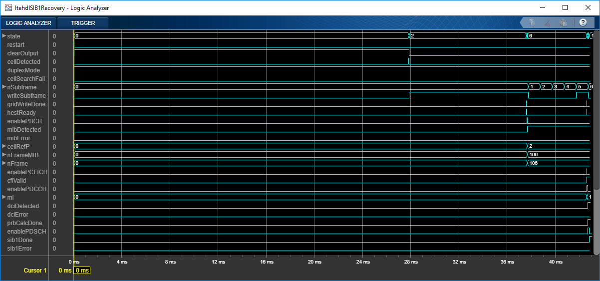
The CONTROL subsystem tracks the state of the decoder through the different channel processing stages, enabling each of the indexing and decoding subsystems in turn. The subframe number and frame number are taken as inputs, allowing the frameCount function to track the System Frame Number (SFN). The subframe and frame numbers are used to determine when channels will be available for decode (e.g. SIB1 is only transmitted on subframe 5 of even numbered frames). The decoderState MATLAB Function block implements a simple state machine that keeps track of which processing stages have been completed, and which stage to enable next. The state of the decoder is output from the controller, and is parsed by the stateViewer MATLAB Function block at the top level of the model to produce human readable messages.
When the received signal is in TDD mode the CONTROL subsystem manages the blind search of each of the TDD configurations, running the PDCCH Indexing and PDCCH Decoding subsystems for each of the three possible mi values. The different mi values {0,1,2} result in different PHICH allocations, hence different PDCCH allocations. The PDCCH allocations are calculated, and the PDCCH decode attempted for each mi value, until a SIB1 DCI message is found, or all of the possibilities are exhausted.

Results and Display
The simulation model is configured to stop the simulation under a number of conditions:
If the cell search does not find any cells.
If the MIB detection has an error.
If a SI-RNTI DCI message is not detected during the PDCCH search.
At the end of the PDSCH decoding attempt.
If the SIB1 message is successfully decoded, it is output from the sib1Bits port, with the sib1BitsValid port indicating when the output is valid. The data is buffered and sent to the MATLAB workspace.
The LTE HDL SIB1 Receiver State Information figure window displays text messages indicating the current state of the decoder. The state of the system is tracked by the CONTROL subsystem, with the decoderState signal passed up to the top level of the model where the statePrint MATLAB Function block generates the text info messages.

The display blocks in the top level of the model show some of the key parameters decoded by each of the channel processing stages. A number of the key control signals, from within the CONTROL subsystem, are logged for viewing with the logic analyzer.
HDL Code Generation and Verification
To generate the HDL code for this example you must have an HDL Coder™ license. Note that test bench generation for this example takes a long time due to the length of the simulation required to create the test vectors.
HDL code for the HDL LTE SIB1 subsystem was generated using the HDL Workflow Advisor IP Core Generation workflow for an AMD® Zynq®-7000 ZC706 evaluation board, and then synthesized. The post place and route resource utilization results are shown below. The design met timing with a target clock frequency of 150MHz. Using the workflow advisor IP core generation workflow allows the input and output ports to be mapped to AXI4-Lite registers, reducing the number of FPGA IO pins required, and allows the design to be split between hardware and software.
       Resource        Usage
    _______________    ______

    Slice Registers    104299
    Slice LUTs          64678
    RAMB18                 55
    RAMB36                191
    DSP48                 138
For more information see Prototype Wireless Communications Algorithms on Hardware
Limitations
The stateViewer MATLAB function block is not supported for simulation in rapid accelerator mode. This block can be removed or commented out if rapid accelerator simulation is required.
References
1. 3GPP TS 36.211, "Physical Channels and Modulation"