Create Custom OFDM Resource Grid
This example shows how to design and verify a model which modulates and demodulates a custom OFDM resorce grid for HDL code generation.
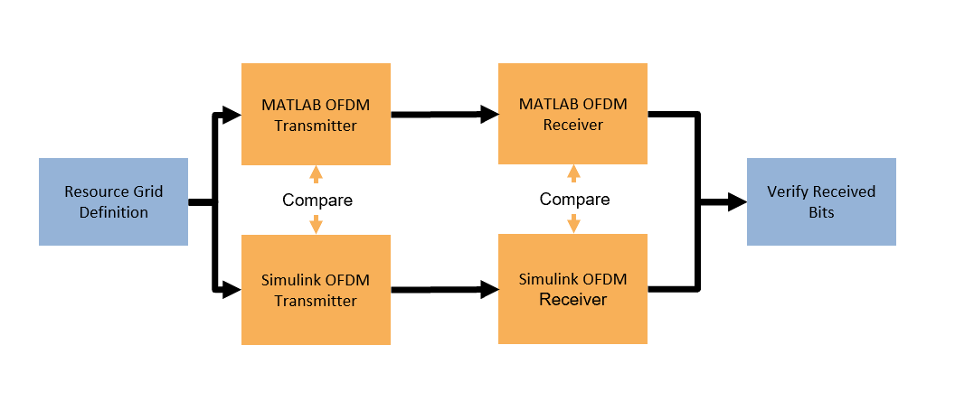
First, the example introduces the structure of the OFDM grid, and how to add contents to the grid. Then, the example describes transmitter and receiver designs that each have a MATLAB reference and a Simulink model that is suitable for HDL code generation. The MATLAB reference explores the design space and provides test vectors. The example runs the Simulink transmitter and receiver subsystems connected together and then compares the results to MATLAB. Finally, the example shows the results from HDL code generation.
This example is part of a related set of examples for custom OFDM communication systems. For more information see Custom OFDM Reference Applications Overview.
Resource Grid Definition
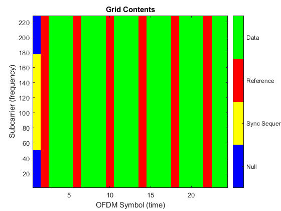
The first stage of designing a custom OFDM communication system is to define the structure and contents of the resource grid. The resource grid is defined as a 2-D matrix in the frequency domain with number of subcarriers (Nsc) rows and number of OFDM symbols (NofdmSyms) columns. OFDM modulation converts this resource grid from the frequency domain to the time domain. The FFT size (Nfft), subcarrier spacing (scs), and the length of the cyclic-prefix (Ncp) determine the symbol bandwidth and duration. The Nfft and Ncp values are in samples, and the scs in kHz. For more information on OFDM see OFDM Modulation Using MATLAB.
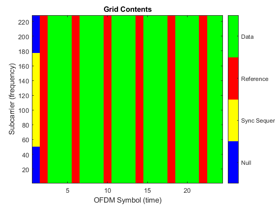
The OFDM resource grid is populated by modulated symbols of a specified signal type on each resource element. A resource element is one subcarrier in one OFDM symbol. This allows for the design of custom communication systems where many different signal types are combined to satisfy the system requirements. This example includes the following three signal types. Any resource element without a specified signal type is filled with a null.
Synchronization Sequence - The synchronization sequence is created using a maximal length PN sequence that has good auto-correlation properties. It is placed in the first OFDM symbol of the resource grid to allow the receiver to perform synchronization before data reception.
Reference Symbols - The reference symbols are transmitted interspersed with the data symbols to allow the receiver to estimate and equalize the channel.
Data Symbols - The data symbols carry the information in the resource grid.
This code defines the OFDM resource grid. The example defines the overall grid structure, and then the indices for each signal type in the resource grid. Additionally, the synchronization sequence is generated from a maximal-length PN sequence.
%% Define OFDM Constants

% Define OFDM Resource Grid
Nfft = 256;                  % FFT size in samples
Ncp = 64;                    % Cyclic-prefix length in samples
Nsym = Nfft+Ncp;             % Time domain OFDM symbol length in samples
scs = 30;                    % Subcarrier spacing in kHz
Nsc = 228;                   % Number of active subcarriers in the resource grid
NofdmSyms = 24;              % Number of OFDM symbols in the resource grid
Nguard = (Nfft/2) - (Nsc/2); % Number of guard subcarriers on each edge the resource grid

ofdmSampleRate = scs*1e3*Nfft;

% Define OFDM Grid Signals

% Synchronization Sequence

% Generate constant synchonization sequence from maximum length sequence
syncSeqGen = comm.PNSequence("Polynomial",[7 6 0],"InitialConditions",[1 1 0 1 1 0 1],"SamplesPerFrame",127);
syncSeq = syncSeqGen();
syncSeq = qammod(syncSeq,2);

gridOffset = floor((Nsc-length(syncSeq))/2);
ssIdx = (1:length(syncSeq)).'+gridOffset;

% Reference Symbols
refOFDMIdx = 2:4:NofdmSyms;
refSCIdx = repmat((1:Nsc).',length(refOFDMIdx),1);

refIdx =  [refSCIdx reshape(repmat(refOFDMIdx,Nsc,1),[],1)];
refIdx = sub2ind([Nsc,NofdmSyms],refIdx(:,1),refIdx(:,2));

% Data Symbols
dataOFDMIdx = setdiff(2:NofdmSyms,refOFDMIdx);
dataSCIdx = repmat((1:Nsc).',length(dataOFDMIdx),1);

dataIdx =  [dataSCIdx reshape(repmat(dataOFDMIdx,Nsc,1),[],1)];
dataIdx = sub2ind([Nsc,NofdmSyms],dataIdx(:,1),dataIdx(:,2));

% Define signal type of each resource element
resourceElemType = zeros(Nsc,NofdmSyms);
resourceElemType(ssIdx) = 1;
resourceElemType(refIdx) = 2;
resourceElemType(dataIdx) = 3;
OFDM Transmitter MATLAB Reference
The OFDM transmitter performs two operations.
Resource grid construction - uses the variables from the resource grid definition to create the empty resource grid, generate the symbols for each signal type and add them onto the specified elements. This example generates random bits for the data and reference signals, and then performs QPSK modulation to create the symbols for insertion.
OFDM modulation - uses the
ofdmmodfunction to convert the resource grid into a time domain waveform to transmit. The resource grid is centered in the FFT by adding guard subcarriers with thenullIndicesinput.
This code implements the OFDM transmitter. The code is a behavioral reference for the Simulink model.
%% OFDM Transmitter MATLAB

% Create empty resource grid
txGridML = zeros(Nsc,NofdmSyms);

% Synchronization Sequence
txGridML(ssIdx,1) = syncSeq;

% Reference Symbols
refBits = randi([0 1],length(refIdx)*2,1);
refSyms = qammod(refBits,4,[2 3 0 1],UnitAveragePower=1,InputType="bit");

txGridML(refIdx) = refSyms;

% Data Symbols
txBits = randi([0 1],length(dataOFDMIdx)*Nsc*2,1);
txDataSyms = qammod(txBits,4,[2 3 0 1],UnitAveragePower=1,InputType="bit");

txGridML(dataIdx) = txDataSyms;

% OFDM Modulate
firstSC = Nguard + 1;
nullIndices = [1:(firstSC-1) (firstSC+Nsc):Nfft].';
txWaveformML = ofdmmod(txGridML,Nfft,Ncp,nullIndices);
OFDM Transmitter Simulink
The OFDM transmitter algorithm is implemented in Simulink for HDL code generation. The algorithm is converted into a fixed-point streaming design with control signals. The model consists of three stages:
Grid Structure - This area of the model creates the streaming control signals that construct the resource grid. The
scNumandsymNumoutputs from theFrame Counterindicate the current position in the resource grid. TheFrame Counterserializes the resource grid first in the subcarrier dimension, and then along OFDM symbols. The resource grid definition from MATLAB is stored in theResource Element Typelookup table. The lookup table determines which signal type is present on the current element. TheFrame Countergenerates the valid signal required to pace the samples through the system. TheFrame Counteris paused when theenableinput port is zero. This signal controls the duty cycle of the transmitted signal.Grid Contents - This area of the model contains lookup tables with the Synchronization, Reference, and Data symbols. A counter is used per signal type to increment through each lookup table and output the next symbol. Finally, the signal types are multiplexed together to form the input to the OFDM modulator.
OFDM Modulator - The OFDM modulator block creates the time-domain transmitter waveform. It is parameterized by the resource grid definition and performs all stages of OFDM modulation. The OFDM modulator fixed-point scaling is designed to preserve the data type between the input and the output.
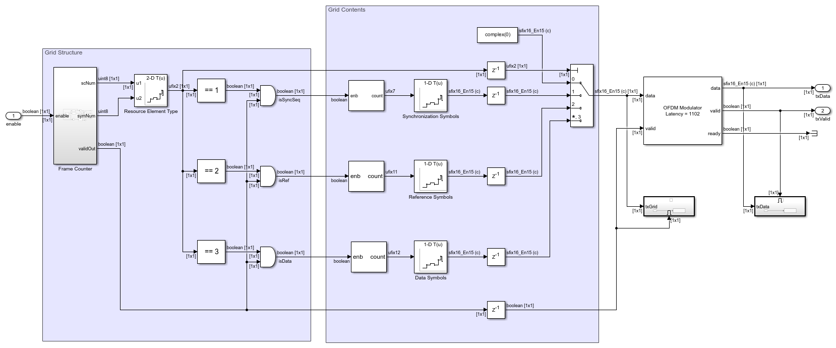
When converting from frame-based MATLAB code to a streaming Simulink model, the pacing of data with control signals must be considered. This example uses a single Simulink rate to implement the whole algorithm - this rate represents the clock in the generated HDL code. The output from the transmitter will feed the digital-to-analog converter (DAC) when deployed on the target board, and the same clock may drive both components. Therefore, the transmitter must be capable of producing a valid output sample every clock cycle, after an initial latency. This constraint defines the valid behavior through the model.
The txValid signal from the transmitter is the output from the OFDM modulator. The OFDM modulator block is designed to meet this requirement with a constant valid output, if the input data is correctly paced. OFDM modulation increases the length of the output relative to the input by adding guard subcarriers and the cyclic-prefix to the signal. For an input length of Nsc, the output length is Nsc + Ncp + Nguard * 2. In a streaming design this means the output takes more cycles than the input. Therefore, a gap of Ncp + Nguard * 2 cycles must be left between each input to allow for the OFDM modulator to finish outputting the previous OFDM symbol. If the input data stalls, the output valid will fall and the DAC will not receive data. Conversely, if the input data is provided too fast then the OFDM modulator will drop the data. Both of these outcomes result in data loss from the transmitter. The data pacing is handled by the Frame Counter valid output, the valid is high for Nsc cycles and then goes low for Nsym - Nsc cycles. This duty cycle ensures that the output from the transmitter will stay high. A timing diagram of the input and output from the OFDM modulator, with the corresponding valid signals, is shown.

OFDM Receiver MATLAB Reference
The OFDM Receiver receives the transmitted waveform directly from the transmitter. This zero impairment environment simplifies the receiver as practical synchronization is not required. Additionally, channel estimation is not required to recover the data bits and they can be directly demodulated from the data symbols. The receiver performs two operations to recover each signal type from the received grid.
OFDM Demodulation - uses the
ofdmdemodfunction to reverse the OFDM modulation and recover the resource grid.Resource grid extraction - slices the received grid back into the synchronization sequence, reference symbols, and data symbols using the resource grid definition.
This code implements the OFDM receiver. The code is a behavioral reference for the Simulink model.
%% OFDM Receiver MATLAB

ofdmDemodInML = txWaveformML;
rxGridML = ofdmdemod(ofdmDemodInML,Nfft,Ncp,Ncp,nullIndices);

rxSyncSeqML = rxGridML(ssIdx);
rxRefML = rxGridML(refIdx);
rxDataML = rxGridML(dataIdx);
OFDM Receiver Simulink
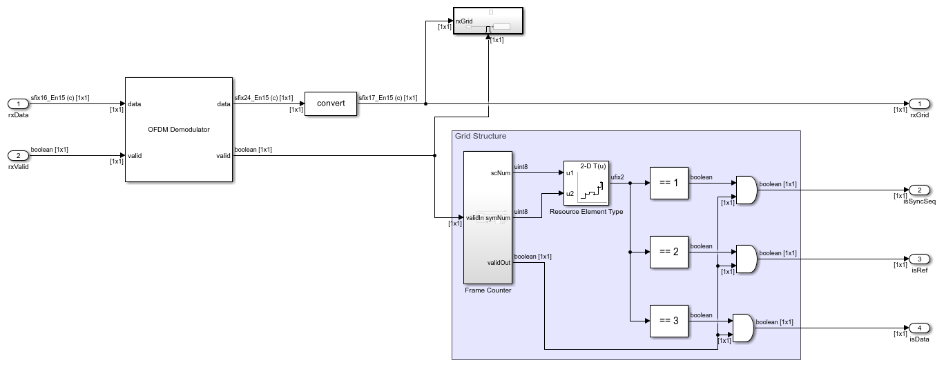
The OFDM receiver algorithm is implemented in Simulink for HDL code generation. The algorithm is converted into a fixed-point streaming design with control signals. The model consists of two stages:
OFDM Demodulator - The OFDM demodulator block reconstructs the resource grid from the time-domain received waveform. It is parameterized by the resource grid definition and performs all stages of OFDM demodulation. The OFDM demodulator output wordlength increases by log2 of the FFT size to account for internal scaling. Because the OFDM modulator and demodulator are directly connected the two resource grids have identical scaling, so the wordlength growth can be discarded. However, fixed-point quantization and rounding errors can lead to a small increase in the received grid's dynamic range so one bit of growth is preserved.
Grid Structure - This area of the model is the mirror of the grid structure area of the transmitter. It separates the received resource grid into each of its signal types. This is performed using the
Frame Countersubsystem and theResource Element Typelookup table. TheFrame Counterdoes not require the valid pacing design from the transmitter. The output valid matches the input valid, excluding the removal of elements containing nulls.
Run OFDM Grid Construction
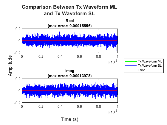
The OFDM grid construction simulation runs the OFDM transmitter and receiver MATLAB reference and Simulink model. Intermediate signal tap points in the Simulink model are compared with MATLAB to verify the numerical equivalence of the two implementations. To verify the functionality of the entire system, the transmitted bits are compared to the received bits.
runOFDMGridConstruction;
Running ofdmGridConstruction.slx
....................

Simulink received bits match transmitted bits.


HDL Code Generation and Implementation Results
To generate the HDL code for this example, you must have the HDL Coder™ product. Use the makehdl and makehdltb commands to generate HDL code and an HDL test bench for the ofdmGridConstruction/OFDM Transmitter and ofdmGridConstruction/OFDM Receiver subsystems. The resulting HDL code was synthesized for a Xilinx® Zynq® UltraScale+ RFSoC ZCU111 evaluation board. The table shows the post place and route resource utilization results. The design meets timing with a clock frequency of 245.76 MHz.
Resource utilization:
       Resource        OFDM Transmitter    OFDM Receiver
    _______________    ________________    _____________

    Slice Registers          5637              5829
    Slice LUTs               3352              3077
    RAMB18                      2                 2
    RAMB36                     10                 0
    DSP48                      12                12