SDRu Transmitter
Send data to USRP device
Libraries:
Wireless Testbench Support Package for NI USRP Radios
Description
Add-On Required: This feature requires the Wireless Testbench Support Package for NI USRP Radios add-on.
The SDRu Transmitter block supports communication between Simulink® and a USRP™ E320, N3xx series, X3xx series, or X410 radio, enabling simulation and development for various software-defined radio applications. For USRP 200-series radios, see the SDRu Transmitter block from Communications Toolbox™ Support Package for USRP Radio.
The SDRu Transmitter block accepts a column vector or matrix input signal from Simulink and transmits signal and control data to a USRP board using the Universal Hardware Driver (UHD™) from Ettus Research™. The SDRu Transmitter block is a Simulink sink that takes data from a model and sends it to a USRP board. The first call to this block can contain transient values, in this case the resulting packets contain undefined data.
This block diagram illustrates how Simulink, SDRu Transmitter and Receiver blocks, and USRP hardware interface.
If your computer is not connected to any USRP hardware, you can still use this block to develop a model that propagates sample time and data type information. To propagate this information, select Simulation >> Update diagram.
For information about the USRP hardware products that interface with this block, see Supported Radio Devices.
This icon shows all ports, including optional ones: ![]()
Ports
Input
Input data sent to the radio hardware, specified as a column vector or
matrix. For a single channel radio, data is a
column vector. For a multichannel radio, data is a
matrix, where each column contains a channel of data. The range of
values for data are [-1 1] for
double or single precision
data and [-32768, 32767] for int16
data.
Dependencies
To specify the output data type, use the Output data type parameter.
Data Types: int16 | single | double
Complex Number Support: Yes
Center frequency setting in Hz, specified as a positive scalar.
Example:
88.9e6 tunes the transmitter to a center frequency of
88.9 MHz.
Dependencies
To enable this port, set Source of center
frequency parameter to Input
Port.
Data Types: double
Local oscillator (LO) offset in Hz, specified as a scalar.
Example:
10 sets the LO offset to 10 Hz.
Dependencies
To enable this port, set Source of LO offset
parameter to Input Port.
Data Types: double
Transmitter gain setting in dB, specified as a scalar or vector. The valid range of this gain depends on the RF daughterboard of the USRP device.
Transmitter gain setting accounts combined analog and digital transmitter gains of the USRP hardware.
For a single channel, specify the value for the gain as a scalar in dB.
For multiple channels that use the same gain value, specify the gain as a scalar in dB. The gain is set by scalar expansion.
For multiple channels that use different gains, specify the values in a vector, for example,
[5 12]. The Nth element of the vector is applied to the Nth channel specified by Channel mapping.
Example:
10 sets the transmitter gain level to 10
dB.
| USRP Radio Series | Rx Gain Valid Range (in dB) | Tx Gain Valid Range (in dB) |
|---|---|---|
| USRP E320 | 0 to 76 dB | 0 to 89.8 dB |
| USRP N300 and USRP N310 |
|
|
| USRP N320 and USRP N321 | 0 to 60 dB (1 MHz to 6 GHz) | 0 to 60 dB (1 MHz to 6 GHz) |
| USRP X3xx Series | The gain value for X3xx series radios varies depending on the RF daughterboard. | |
| USRP X410 | 0 to 60 dB | 0 to 60 dB |
For USRP X3xx series radios, the gain value depends on the RF daughterboard.
| RF daughterboard | Rx Gain Valid Range (in dB) | Tx Gain Valid Range (in dB) |
|---|---|---|
| SBX | 0 to 31.5 dB | 0 to 31.5 dB |
| WBX | 0 to 31.5 dB | 0 to 31.5 dB |
| UBX | 0 to 31.5 dB | 0 to 31.5 dB |
| CBX | 0 to 31.5 dB | 0 to 31.5 dB |
| TwinRX | 0 to 93 dB | 0 to 93 dB |
| TVRX |
| - |
| TVRX2 | 0 to 30 dB | - |
Dependencies
To enable this port, set Source of gain
parameter to Input Port.
Data Types: double
Output
Data discontinuity flag, returned as one of these values.
0— Data samples are not lost.1— Data samples are lost.
Use this port as a diagnostic tool to determine real-time operation of the SDRu Transmitter block. If your model is not running in real time, you can adjust parameters that reduce the number of transported samples. To approach or achieve real-time performance, you can increase the interpolation factor.
Dependencies
To enable this port, select Enable overrun output port.
Lock status of the USRP radio to the 10 MHz clock signal, returned as one of these Boolean values.
0— The USRP radio is not locked to the 10 MHz clock signal of an external clock source or a global positioning system disciplined oscillator (GPSDO).1— The USRP radio is locked to the 10 MHz clock signal of an external clock source or a GPSDO.
Dependencies
To enable this port, select the Enable ref_locked output port parameter.
Data Types: Boolean
Lock status of the GPSDO to the GPS constellation, returned as one of these Boolean values.
0— The GPSDO is not locked to the GPS constellation.1— The GPSDO is locked to the GPS constellation.
Dependencies
To enable this port, select the Enable gps_locked output port parameter.
Data Types: Boolean
Parameters
When you set block parameter values, the SDRu Transmitter block first checks that the values have the correct data types. Even if the values pass those checks, the values can still be out of range for the radio hardware. In that case, the radio hardware sets the actual value as close to the specified value as possible. When you next synchronize the block with the radio hardware by clicking Info, a dialog box open to display the actual values along with other radio information.
If a parameter is listed as tunable, then you can change its value during simulation.
Radio Connection
Radio to configure, specified as one of these options.
E320— A connected USRP E320 radio. (since R2025a)N300— A connected USRP N300 radio.N310— A connected USRP N310 radio.N320/N321— A connected USRP N320 or USRP N321 radio.X300— A connected USRP X300 radio.X310— A connected USRP X310 radio.X410— A connected USRP X410 radio. (since R2025a)
IP address of the radio hardware, specified as a dotted quad expression.
This parameter must match the physical IP address of the radio hardware assigned when you set up your radio using the Radio Setup wizard. If you configure the radio hardware with an IP address other than the default, update IP address accordingly.
The IP address list displays IP addresses for USRP devices attached to the host computer. To specify another known dotted quad IP address, enter it directly into this field.
Refresh the list of all connected devices to update the IP address list. The updated list retains the value in focus before Refresh Device List is selected, even if the device with that setting was disconnected.
Provides information about the Platform of the radio associated with IP address. When you select the Info button, a new dialog box opens with information about the specified device.
Radio Properties
Channel output mapping for radio or bundled radios, specified as a positive integer scalar or vector. This table shows valid values for various radio platforms.
| Platform Value | Channel mapping Value |
|---|---|
|
|
|
|
|
|
|
|
|
|
|
|
When Channel Mapping is a scalar,
1, or 2, the radio operates in
single input single output (SISO) mode. When Channel
Mapping is a vector, the radio operates in multiple input
multiple output (MIMO) mode.
When IP Address contains multiple IP addresses, the channels defined by Channel Mapping are ordered first by the order in which the IP addresses appear in the list and then by the channel order within the same radio.
For example, if Platform is
"X300" and IP Address is
"192.168.20.2, 192.168.10.3", then the
Channel Mapping must be [1 2 3
4]. Channels 1 and 2 of the bundled radio refer to
channels 1 and 2 of the radio with IP address 192.168.20.2,
respectively. Channels 3 and 4 of the bundled radio refer to channels 1
and 2 of the radio with IP address 192.168.10.3, respectively.
Data Types: double
Select source of center frequency, specified as:
Dialog— Set the center frequency using the Center frequency (Hz) parameter.Input port— Set the center frequency using the fc input port.
RF center frequency in Hz, specified as a nonnegative finite scalar or vector of nonnegative finite scalars. The valid range of this parameter depends on the RF daughterboard of the USRP device.
For a single channel (SISO), specify the value for the center frequency as a scalar.
For multiple channels (MIMO) that use the same center frequency, specify the center frequency value as a scalar. The center frequency is set by scalar expansion.
For multiple channels (MIMO) that use different center frequencies, specify the values in a vector. The ith element of the vector is applied to the ith channel specified by Channel mapping.
| USRP Radio Series | Valid Range (Hz) | |
|---|---|---|
| USRP E320 | 70 MHz to 6 GHz | |
| USRP N300 and USRP N310 | 10 MHz to 6 GHz | |
| USRP N320 and USRP N321 | 3 MHz to 6 GHz | |
| USRP X3xx Series | The center frequency value for X3xx series radios varies depending on the RF daughterboard. | |
| USRP X410 | 1 MHz to 7.2 GHz | |
For USRP X3xx series radios, the center frequency value depends on the RF daughterboard.
| RF daughterboard | Valid Range (Hz) |
|---|---|
| LFRX | 0 to 30 MHz |
| LFTX | 0 to 30 MHz |
| SBX | 400 MHz to 4.4 GHz |
| WBX | 50 MHz to 2.2 GHz |
| UBX | 10 MHz to 6 GHz |
| CBX | 1.2 GHz to 6 GHz |
| TwinRX | 10 MHz to 6 GHz |
| TVRX | 50 MHz to 860 MHz |
| TVRX2 | 50 MHz to 860 MHz |
Note
The channels corresponding to the same RF daughterboard of a USRP N300 or N310 radio must have the same center frequency.
For a MIMO scenario, the center frequency for a USRP N300 radio must be a scalar. You cannot specify the frequencies as a vector.
Dependencies
To enable this parameter, set the Source of center
frequency to
Dialog.
Data Types: double
Select source of LO offset, specified as:
Dialog— Set the LO offset using the LO offset (Hz) parameter.Input port— Set the LO offset using the LO offset input port.
Offset frequency for the local oscillator, specified as a scalar or vector. The valid range of this parameter depends on the RF daughterboard of the USRP device.
This figure shows that the local oscillator offset affects the intermediate center frequency in the USRP hardware. It does not affect the transmitted center frequency.
fLO offset is the local oscillator offset frequency.
fcenter represents the center frequency specified by the block.
To move the center frequency away from interference or harmonics generated by the USRP hardware, use the LO offset.
For a single channel (SISO), specify the value for the LO offset as a scalar.
For multiple channels (MIMO), the LO offset must be zero. This restriction is due to a UHD limitation. You can specify the LO offset as a scalar or as a vector.
Dependencies
To enable this parameter, set Source of LO
offset to Dialog.
Select source of gain, specified as:
Dialog— Specify the gain using the Gain (dB) parameter.Input port— Specify the gain using the gain input port.
Transmitter gain in dB, specified as a scalar or vector. The valid range of this gain depends on the RF daughterboard of the USRP device.
Set the value of gain based on the Channel Mapping configuration:
For a single channel (SISO), specify the gain as a scalar.
For multiple channels (MIMO) that use the same gain value, specify the gain as a scalar. The gain is set by scalar expansion.
For multiple channels (MIMO) that use different gains, specify the values in a row vector. The ith element of the vector is applied to the ith channel specified by Channel Mapping.
Dependencies
To enable this parameter, set Source of gain
to Dialog.
Data Types: double
Pulse per second (PPS) signal source, specified as one of these values.
Internal— Use the internal PPS signal of the USRP radio.External— Use the PPS signal from an external signal generator.GPSDO— Use the PPS signal from a GPSDO.
To synchronize the time for all channels of the bundled radios, you can:
Provide a common external PPS signal to all of the bundled radios and set this parameter to
External.Use the PPS signal from the GPSDO that is available on the USRP radio by setting this parameter to
GPSDO.
To synchronize the USRP time to the valid GPS time, set this parameter to
GPSDO. You must also enable the Ensure sync GPS
time parameter if the GPSDO is not locked to the GPS constellation at the
start of the simulation.
Select this parameter to enable the gpsLocked output port, which indicates the lock status of the GPSDO to the GPS constellation.
Dependencies
To enable this parameter, set the PPS source parameter to
GPDSO.
Select this parameter to ensure that the USRP radio time is synchronized to the valid GPS time.
When you select this parameter, the block checks the lock status of the GPSDO. When the GPSDO is locked to the GPS constellation, the block sets the USRP radio time to the valid GPS time.
Dependencies
To enable this parameter, set the PPS source parameter to
GPSDO.
Clock source, specified as one of these values.
Internal— Use the internal clock signal of the USRP radio.External— Use the 10 MHz clock signal from an external clock generator.GPSDO— Use the 10 MHz clock signal from a GPSDO.
The external clock port is labeled REF IN.
To synchronize the frequency for all channels of the bundled radios, you can:
Provide a common external 10 MHz clock signal to all of the bundled radios and set this parameter to
External.Provide a 10 MHz clock signal from each GPSDO to the corresponding radio and set this parameter to
GPSDO.
Select this parameter to enable the refLocked output port, which indicates the lock status of the USPR radio to the 10 MHz clock signal.
Dependencies
To enable this parameter, set the Clock source parameter to
External or GPDSO.
Master clock rate, specified as a scalar in Hz. The master clock rate is the A/D and D/A clock rate. The valid range of values for this property depends on the radio platform that is connected.
| Platform Value | Supported Master clock rate (Hz) Values |
|---|---|
| Scalar in the range from When you use a USRP E320 radio with two transmit channels or two receive channels, the clock rate must be less than or equal to 30.72e6. This restriction is a hardware limitation for two-channel operations on USRP E320 radios. The default value is
|
|
|
|
|
|
|
|
|
Data Types: double
Interpolation factor for the SDRu transmitter, specified as an integer in the range
[1,1024] with restrictions that depend on the radio you use.
| Radio Device | Supported Interpolation Factors |
|---|---|
USRP E320 (since R2025a) USRP N300 USRP N310 USRP N320 USRP N321 USRP X410 (since R2025a) | 1 |
2 | |
3 | |
Even integer in the range from 4 to 256 | |
Multiple of 4 in the range from 256 to 512 | |
Multiple of 8 in the range from 512 to 1016 | |
USRP X300 USRP X310 | Integer in the range from 1 to 128 |
Even integer in the range from 128 to 256 | |
Multiple of 4 in the range from 256 to 512 | |
Multiple of 8 in the range from 512 to 1016 |
The radio uses the interpolation factor when it upconverts the complex baseband signal to an intermediate frequency (IF) signal.
Option to enable timed transmission and reception. To enable the radio to transmit or receive data after a specified time, select Enable time trigger.
When you select Enable time trigger parameter, you can:
Transmit or receive after the time specified in the Trigger time parameter.
Transmit or receive at the specified GPS time in the Trigger time parameter if you set the PPSSource parameter to
GPSDO.Simultaneously transmit and receive after the time specified in the Trigger time parameter.
Trigger time in seconds, specified as a nonnegative scalar. Specify the trigger time after which you want the radio to transmit or receive data. The Trigger time value must be greater than the current USRP radio time.
When you set the PPS Source parameter to
GPSDO, specify the Trigger time parameter
as the exact GPS time in seconds at which the radio transmits and receives data.
Note
For AD936x-based N3xx USRP radios, you can expect a consistent delay between the specified trigger time and the start of transmission or reception.
Dependencies
To enable this parameter, select the Enable trigger time parameter.
Data
This parameter is read-only.
Baseband sample rate of output signal, in Hz, specified as a scalar.
This parameter displays the computed baseband sample rate derived from the Master clock rate (Hz) and Interpolation factor parameter values. This computation uses the formula, Baseband sample rate = Master clock rate/Interpolation factor. If you change the Interpolation factor during simulation, then the block changes hardware data rate, but does not change the Simulink sample time.
To get more information on sample time, see What Is Sample Time? (Simulink).
Data Types: double
Transport data type, specified as:
int16— Uses 16-bit transport. Achieves higher precision than 8-bit transport.int8— Uses 8-bit transport. Uses a quantization step 256 times larger and achieves approximately two times faster transport data rate than 16-bit transport.
Specifying transport data rate data type as int16, assigns 16 bits
for the in-phase component and 16 bits for the quadrature component, resulting in 32
bits for each complex sample of transport data.
To measure the number of samples lost during transmission, select this parameter.
If your model is not running in real time, you can adjust parameters that reduce the number of transported samples. To approach or achieve real-time performance, you can increase the interpolation factor.
Option to enable burst mode. To produce a set of contiguous frames without an overrun or underrun to the radio, select Enable burst mode. Enabling burst mode helps you simulate models that cannot run in real time.
When burst mode is enabled, specify the desired amount of contiguous data using the Number of frames in burst parameter.
Number of frames in a contiguous burst, specified as a nonnegative integer.
Dependencies
To enable this parameter, select Enable burst mode.
Data Types: double
More About
USRP E320, N300, N321, X300, and X310 support two channels that you can use to transmit and receive data with SDRu blocks. You can use both channels or only a single channel (either channel 1 or 2).
The SDRu Transmitter block receives a matrix signal, where each column is a channel of data of fixed length.
The SDRu Receiver block outputs a matrix signal, where each column is a channel of data of fixed length.
Note
When two TwinRX daughterboards are connected to a USRP X300 or X310 radio, the radio supports up to four channels.
USRP N310 and X410 radios support four channels that you can use to transmit and receive data with SDRu blocks.
The SDRu Transmitter block receives a matrix signal, where each column is a channel of data of fixed length.
The SDRu Receiver block outputs a matrix signal, where each column is a channel of data of fixed length.
You can set the Center frequency, LO offset, and Gain block parameters independently for each channel. Alternatively, you can apply the same setting to all channels. All other block parameter values apply to all channels.
For more information, see Multiple Channel Input and Output Operations.
Run your application with Accelerator or Rapid Accelerator instead of Normal mode. Note that some scopes does not plot data when run in Rapid Accelerator mode.
When you use accelerator or rapid accelerator mode, on the Model Configuration Parameters dialog box, navigate to Compiler optimization level tab, and then set the parameter value to Optimizations on (faster runs).
Performance analysis for SDRu Blocks
Starting in R2022a, the SDRu blocks show improved speed performance with fewer underruns and overruns. For example, you can observe a speedup (in megasamples per second (MS/s)) with fewer underruns or overruns at 10000 samples per frame when you simulate these models in Normal, Accelerator, or Rapid Accelerator mode.
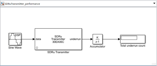
Transmitter performance model
Receiver performance model

The table shows the speedup analysis of these models with no underruns or overruns for USB-based radios and Ethernet-based radios. This speedup analysis is carried out between R2021b and R2022a.
| Transmitter / Receiver | Radio type | R2021b Normal Mode | R2022a Normal Mode | R2021b Rapid Accelerator Mode | R2022a Rapid Accelerator Mode |
|---|---|---|---|---|---|
| Receiver | X-series | 2 MS/s | 50 MS/s | 15.36 MS/s | 61.44 MS/s |
| Transmitter | X-series | 10 MS/s | 30.72 MS/s | 10 MS/s | 40 MS/s |
The models were timed on a Windows® 10, Intel® Xeon® CPU E5-1650 v4 @ 3.60 GHz test system.
Extended Capabilities
C/C++ Code Generation
Generate C and C++ code using Simulink® Coder™.
Version History
Introduced in R2011bYou can now use the SDRu Transmitter block to transmit data using USRP E320 and X410 radios.
Support for NI™ USRP N3xx and X3xx series radio devices has moved from Communications Toolbox Support Package for USRP Radio to Wireless Testbench™ Support Package for NI USRP Radios.
You can now specify trigger time to enable transmission and reception of data at a specified time for a USRP radio. This property is available in the SDRu Transmitter and SDRu Receiver Simulink blocks.
Starting in R2020a, the SDRu Transmitter block removed the interp input port. You can not set the interpolation factor value for this block by using an input port. Instead use the Interpolation factor parameter.
Starting in R2020a, the SDRu Transmitter block removed the Sample time parameter. Use the read-only Baseband sample rate (Hz) parameter instead. This parameter displays the computed baseband sample rate derived from the Master clock rate (Hz) and Interpolation factor parameters.
Beginning with Ettus Research UHD version 003.014.000.000, X3xx series radios do not support a master clock rate value of 120 MHz. Consequently, starting in R2020a, which supports UHD version 003.015.000.000, Communications Toolbox Support Package for USRP Radio does not support a master clock rate value of 120 MHz for X3xx series radios.
For the SDRu Transmitter and SDRu Receiver blocks,
when you select an X3xx series radio for the Platform
parameter, you can no longer set the Master
clock rate (Hz) parameter to 120e6.
See Also
Blocks
Objects
MATLAB Command
You clicked a link that corresponds to this MATLAB command:
Run the command by entering it in the MATLAB Command Window. Web browsers do not support MATLAB commands.
选择网站
选择网站以获取翻译的可用内容,以及查看当地活动和优惠。根据您的位置,我们建议您选择:。
您也可以从以下列表中选择网站:
如何获得最佳网站性能
选择中国网站(中文或英文)以获得最佳网站性能。其他 MathWorks 国家/地区网站并未针对您所在位置的访问进行优化。
美洲
- América Latina (Español)
- Canada (English)
- United States (English)
欧洲
- Belgium (English)
- Denmark (English)
- Deutschland (Deutsch)
- España (Español)
- Finland (English)
- France (Français)
- Ireland (English)
- Italia (Italiano)
- Luxembourg (English)
- Netherlands (English)
- Norway (English)
- Österreich (Deutsch)
- Portugal (English)
- Sweden (English)
- Switzerland
- United Kingdom (English)