Accelerating Development and Testing of High-Speed Optical Integrated Circuits at Fujitsu
By William Walker, Fujitsu Laboratories of America
At Fujitsu Laboratories of America, we use MATLAB® and Instrument Control Toolbox™ to perform automated tests and data analysis. This approach enabled our engineering team to accelerate our production schedules and improve the quality, speed, and reproducibility of our tests during product verification.
Verifying a 40 Gbps Optical Transponder
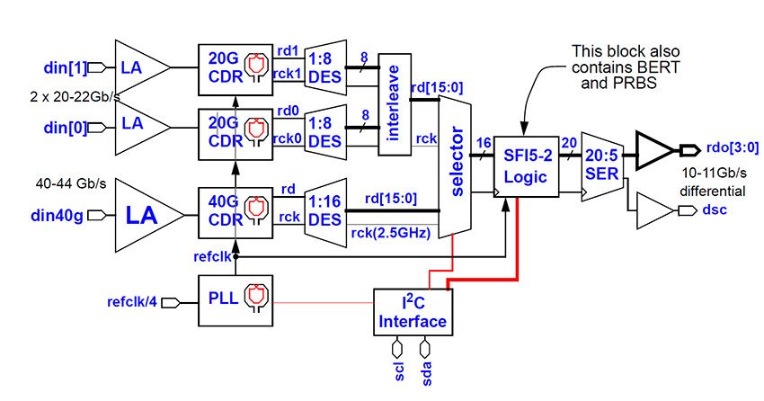
Automated verification played a key role in a recent project—the development of a serializer/deserializer (SERDES) capable of handling 40 gigabits per second (Gbps). The SERDES chip set serves as the foundation for Fujitsu's optical network transponders (Figure 1). It is a low-power, mixed-signal CMOS device with digital logic as well as much more complex analog circuitry for the limiting amplifiers (LAs) and clock data recovery (CDR) components. The system specifications require bit-error rates (BERs) of less than one error per trillion bits.
Prior to fabrication, we extensively simulate the system, but no matter how extensive our simulation, some aspects of the design, such as varactors, inductors, and field-effect transistors (FETs), can only be verified on silicon. When these analog devices are fabricated, their RF parameters can differ significantly from those we used in our simulations. These discrepancies can be a result of the physical layout of the design or of the fabrication process. When they are outside the tolerances accounted for in the design, the chip is unlikely to meet our quality standards.
We rely on automated testing to quickly and accurately characterize the devices on chip and extract the relevant analog and RF parameters. By quantifying the discrepancies between our design and the silicon returned from the foundry, we can refine the design and improve the chip's overall performance.
Test Automation
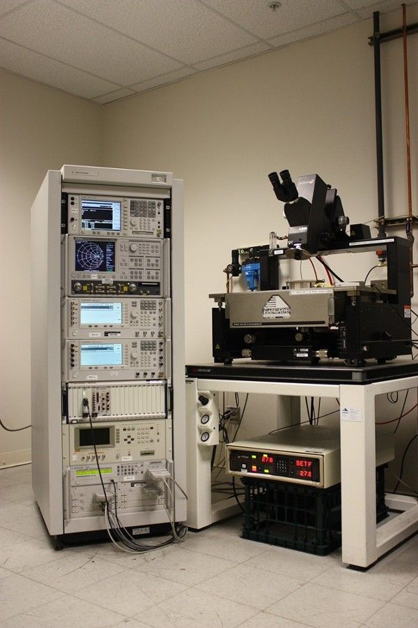
In our labs we deploy a wide range of test equipment, including signal generators, source-monitor units, spectrum analyzers, vector network analyzers, and digital oscilloscopes (Figure 2).
Manual tests, and even semi-automated tests using vendor instrument control software, are time-consuming, tedious, and labor-intensive. Automatically controlling different vendors' software is a very challenging task, especially when equipment from different vendors is part of the same test suite. More importantly, it is difficult to obtain reproducible test results when an engineer operates the test equipment controls by hand.
For these reasons, each piece of our test equipment is controlled using MATLAB scripts and Instrument Control Toolbox. Although equipment vendors supply software to operate their instruments, and some even ship with built-in Windows PCs, we find that Instrument Control Toolbox is a more effective solution, as it provides a consistent interface to all instruments from a single host computer. Bypassing the vendor interfaces and instead writing MATLAB scripts to perform tests requires a little more effort in the earlier stages, but that investment pays off many times over throughout the project.
Most importantly, using Instrument Control Toolbox from a central host computer enables all the instruments to be operated together in the same test suite, and we can initiate a test suite just by running a script. A test suite typically makes a series of measurements under different operating conditions—for example, measurements at different frequencies—and uses multiple pieces of equipment to measure different device properties.
The data from a test needs to be processed immediately to make a go/no-go decision about subsequent tests. For example, if a short-circuit is detected, there is no point in continuing on to the next test. Our MATLAB based software is capable of sophisticated data analysis, enabling us to make complex go/no-go decisions. Only by integrating data analysis and software control of instruments can we achieve this level of automation.
The object-oriented programming capabilities of the MATLAB language have proved particularly useful in our test environment. We create a MATLAB class for each test instrument. These classes make it easier to save state information during a test and return to it later if we have to interrupt a test for any reason. When we acquire a new test instrument, we can create a class for it by altering an existing MATLAB class for a similar piece of equipment. Because the classes share a common interface, we are usually up and running with any new instrument within a day. This approach also makes it easier and faster for us to create new test scripts.
Device Testing
To achieve the accuracy we need from our circuit simulations, we test and characterize on-chip devices. This process relies on MATLAB and Instrument Control Toolbox to collect and process volumes of test data.
By automating the tests using MATLAB, we can control the precise sequence and timing of the steps executed for each test procedure. Parameter sweeps become straightforward to script and execute. Test results are recorded automatically, eliminating human error, and the steps used to obtain them are logged. For example, we have a script that collects data from the vector network analyzer and records scattering parameters (S-parameters) at a range of frequencies.
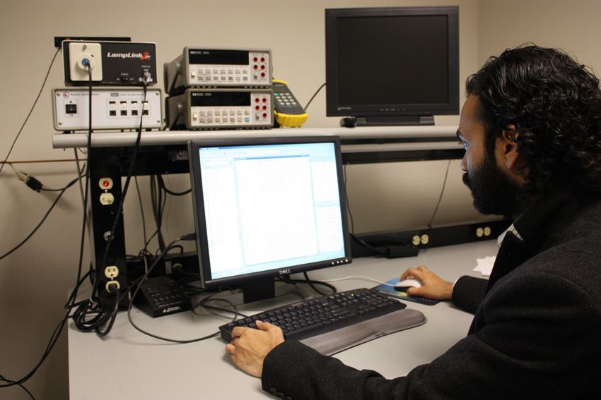
Our test setup enables us to use multiple pieces of test equipment without physically changing the connection to the device under test. For example, we can measure S-parameters and the power spectrum of the device on different instruments using the same physical connection. This makes our testing much faster. We can schedule several tests to run sequentially and then go to lunch or work on another task. When we return, the results are waiting for us, ready to be analyzed (Figure 3).
As well as improving our testing process, test automation makes it practical to do some types of testing. In many cases, manual testing is simply not feasible. For example, characterizing an FET manually would take 10 times longer than with automated scripts. Moreover, if we repeated the characterization manually, we would probably get different results because of slight differences in the test setup process. By contrast, we can use the same automated script and get consistent results every time. In fact, the results are so reliable that we use them to identify test equipment that is aging and in need of recalibration.
Circuit Testing
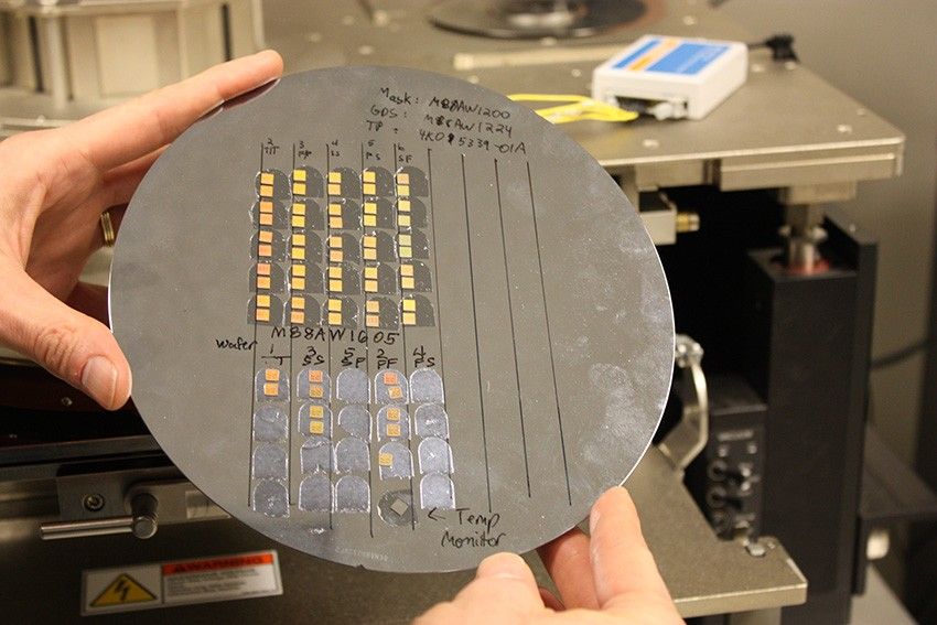
We also use MATLAB and Instrument Control Toolbox to initiate and manage built-in self-tests via the chip's JTAG (IEEE 1149.1) and I2C interfaces (Figure 4).
For example, a typical script for a chip just back from the foundry would start with simply powering the chip up and measuring the current draw. If the device is drawing too much current, we know that it has a short circuit, and the test terminates. If not, the MATLAB script proceeds to verify the test logic using a predefined procedure before beginning basic tests of the device.
Because our SERDES chip operates at such high data rates, using industrial testers to perform BER tests is prohibitively expensive. Instead, we have integrated pseudorandom bit sequence (PRBS) generators and bit error rate test (BERT) circuits into our SERDES ICs. MATLAB scripts use the I2C interface to instruct the PRBS what pattern to send to the CDR and for how many cycles. At the end of the test, the script reads the error count from BERT registers and logs the data.
Analyzing the Results and Looking Ahead
We use the device characterization results from our automated tests to improve our device modeling and design. We make changes to our simulation models to more closely reflect the measured data and then revise the design. Because the next iteration of the design is based on more accurate data, its performance more closely matches our specification.
Foundry costs continue to rise, and few companies can afford to debug in silicon. Our long-term goal is to have a single tape-out with no respins. Using our automated verification process, we have already reached our near-term objectives of reduced development time and rapid, accurate device characterization.
Published 2011 - 91885v01


