同步信号块和突发
此示例说明了如何生成同步信号块 (SSB),以及如何生成多个 SSB 以形成同步信号突发(SS 突发)。其中将创建形成同步信号块的信道和信号(主同步信号和辅同步信号、物理广播信道),并将其映射到表示该块的矩阵中。最后,将创建表示同步信号突发的矩阵,并创建突发中的每个同步信号块并将其映射到矩阵中。
SS/PBCH 块
TS 38.211 第 7.4.3.1 节将同步信号/物理广播信道 (SS/PBCH) 块定义为 240 个子载波和 4 个 OFDM 符号,其中包含以下信道和信号:
主同步信号 (PSS)
辅同步信号 (SSS)
物理广播信道 (PBCH)
PBCH 解调参考信号 (PBCH DM-RS)
在其他文档中,例如在 TS 38.331 中,SS/PBCH 称为“同步信号块”或“SS 块”。
创建一个表示 SS/PBCH 块的 240×4 矩阵:
ssblock = zeros([240 4])
ssblock = 240×4

     0     0     0     0
     0     0     0     0
     0     0     0     0
     0     0     0     0
     0     0     0     0
     0     0     0     0
     0     0     0     0
     0     0     0     0
     0     0     0     0
     0     0     0     0
     0     0     0     0
     0     0     0     0
     0     0     0     0
     0     0     0     0
     0     0     0     0
      ⋮
主同步信号 (PSS)
为给定的小区标识创建 PSS:
ncellid = 17;
pssSymbols = nrPSS(ncellid)
pssSymbols = 127×1

    -1
    -1
    -1
    -1
    -1
    -1
     1
     1
     1
    -1
    -1
    -1
     1
    -1
    -1
      ⋮
变量 pssSymbols 是一个列向量,其中包含 PSS 的 127 个 BPSK 符号。
创建 PSS 索引:
pssIndices = nrPSSIndices;
变量 pssIndices 是一个列向量,其大小与 pssSymbols 相同。pssIndices 的每个元素中的值是 SS/PBCH 块中位置的线性索引,pssSymbols 中的相应符号应当映射到该块。因此,通过使用线性索引来选择 SS/PBCH 块矩阵的正确元素,可利用简单的 MATLAB 赋值来执行 PSS 符号到 SS/PBCH 块的映射。请注意,将向 PSS 符号应用缩放因子 1,以表示 TS 38.211 第 7.4.3.1.1 节中的 :
ssblock(pssIndices) = 1 * pssSymbols;
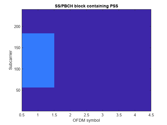
绘制 SS/PBCH 块矩阵以显示 PSS 的位置:
imagesc(abs(ssblock));
clim([0 4]);

axis xy;
xlabel('OFDM symbol');
ylabel('Subcarrier');
title('SS/PBCH block containing PSS');

辅同步信号 (SSS)
按照 PSS 的配置,为小区标识创建 SSS:
sssSymbols = nrSSS(ncellid)
sssSymbols = 127×1

    -1
     1
    -1
    -1
    -1
     1
    -1
     1
    -1
     1
    -1
    -1
    -1
     1
     1
      ⋮
按照用于 PSS 的相同模式,创建 SSS 索引并将 SSS 符号映射到 SS/PBCH 块。请注意,将向 SSS 符号应用缩放因子 2,以表示 TS 38.211 第 7.4.3.1.2 节中的 :
sssIndices = nrSSSIndices;
ssblock(sssIndices) = 2 * sssSymbols;
索引的默认形式是以 1 为基数的线性索引,适用于 MATLAB 矩阵(如之前所示的 ssblock)的线性索引。不过,NR 标准文档采用以 0 为基数的编号方式,通过 OFDM 子载波和符号下标来描述 OFDM 资源。为了便于使用 NR 标准进行交叉检查,索引函数接受允许选择索引样式(线性索引与下标)和基数(以 0 为基数与以 1 为基数)的选项:
sssSubscripts = nrSSSIndices('IndexStyle','subscript','IndexBase','0based')
sssSubscripts = 127×3 uint32 matrix

   56    2    0
   57    2    0
   58    2    0
   59    2    0
   60    2    0
   61    2    0
   62    2    0
   63    2    0
   64    2    0
   65    2    0
   66    2    0
   67    2    0
   68    2    0
   69    2    0
   70    2    0
      ⋮
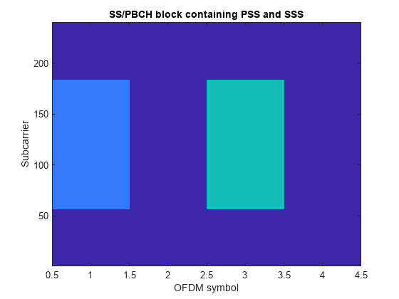
从下标可以看出,SSS 位于 SS/PBCH 块的 OFDM 符号 2(以 0 为基数)中,从子载波 56 开始(以 0 为基数)。
再次绘制 SS/PBCH 块矩阵,以显示 PSS 和 SSS 的位置:
imagesc(abs(ssblock));
clim([0 4]);
axis xy;
xlabel('OFDM symbol');
ylabel('Subcarrier');
title('SS/PBCH block containing PSS and SSS');

物理广播信道 (PBCH)
PBCH 传送通过执行 MIB 的 BCH 编码而创建的长度为 864 比特的码字。有关 BCH 编码的详细信息,请参阅函数 nrBCH 和 nrBCHDecode 并在 NR Cell Search and MIB and SIB1 Recovery示例中了解其用法。此处使用了由 864 个随机比特组成的 PBCH 码字:
cw = randi([0 1],864,1);
PBCH 调制包括 TS 38.211 第 7.3.3 节所述的以下步骤:
加扰
调制
映射到物理资源
加扰和调制
如 TS 38.213 第 4.1 节中的小区搜索过程所述,多个 SS/PBCH 块在半帧内发送。将为每个 SS/PBCH 块提供 范围中的一个索引,其中 是半帧中的最大 SS/PBCH 块数。PBCH 的加扰序列根据小区标识 ncellid 进行初始化,用来对 PBCH 码字进行加扰的子序列取决于值 (SS/PBCH 块索引的 2 个或 3 个 LSB),如 TS 38.211 第 7.3.3.1 节中所述。在此示例中,将使用 。函数 nrPBCH 可创建加扰序列的合适子序列,并依次执行加扰和 QPSK 调制:
v = 0;
pbchSymbols = nrPBCH(cw,ncellid,v)
pbchSymbols = 432×1 complex

  -0.7071 + 0.7071i
  -0.7071 + 0.7071i
  -0.7071 + 0.7071i
  -0.7071 - 0.7071i
   0.7071 + 0.7071i
  -0.7071 + 0.7071i
  -0.7071 + 0.7071i
   0.7071 - 0.7071i
   0.7071 + 0.7071i
   0.7071 + 0.7071i
   0.7071 - 0.7071i
  -0.7071 - 0.7071i
   0.7071 - 0.7071i
  -0.7071 + 0.7071i
  -0.7071 + 0.7071i
      ⋮
映射到资源元素
创建 PBCH 索引并将 PBCH 符号映射到 SS/PBCH 块。请注意,将向 PBCH 符号应用缩放因子 3,以表示 TS 38.211 第 7.4.3.1.3 节中的 :
pbchIndices = nrPBCHIndices(ncellid);
ssblock(pbchIndices) = 3 * pbchSymbols;
再次绘制 SS/PBCH 块矩阵,以显示 PSS、SSS 和 PBCH 的位置:
imagesc(abs(ssblock));
clim([0 4]);
axis xy;
xlabel('OFDM symbol');
ylabel('Subcarrier');
title('SS/PBCH block containing PSS, SSS and PBCH');

PBCH 解调参考信号 (PBCH DM-RS)
SS/PBCH 块的最后一个组件是与 PBCH 关联的 DM-RS。与 PBCH 类似,使用的 DM-RS 序列派生自 SS/PBCH 块索引,并且是使用 TS 38.211 第 7.4.1.4.1 节中所述的变量 配置的。此处使用了 :
ibar_SSB = 0;
dmrsSymbols = nrPBCHDMRS(ncellid,ibar_SSB)
dmrsSymbols = 144×1 complex

   0.7071 - 0.7071i
   0.7071 + 0.7071i
  -0.7071 + 0.7071i
  -0.7071 + 0.7071i
   0.7071 - 0.7071i
   0.7071 + 0.7071i
   0.7071 - 0.7071i
  -0.7071 - 0.7071i
  -0.7071 - 0.7071i
   0.7071 + 0.7071i
   0.7071 - 0.7071i
   0.7071 + 0.7071i
   0.7071 - 0.7071i
   0.7071 + 0.7071i
  -0.7071 + 0.7071i
      ⋮
请注意,TS 38.211 第 7.4.1.4.1 节定义了一个中间变量 ,该变量的定义方式与之前针对 PBCH 介绍的 相同。
创建 PBCH DM-RS 索引并将 PBCH DM-RS 符号映射到 SS/PBCH 块。请注意,将向 PBCH DM-RS 符号应用缩放因子 4,以表示 TS 38.211 第 7.4.3.1.3 节中的 :
dmrsIndices = nrPBCHDMRSIndices(ncellid);
ssblock(dmrsIndices) = 4 * dmrsSymbols;
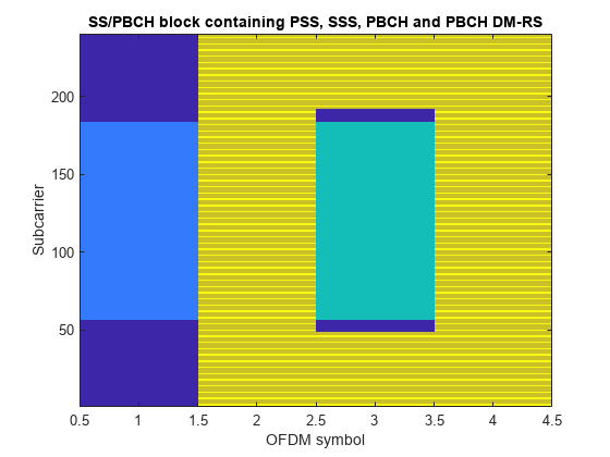
再次绘制 SS/PBCH 块矩阵,以显示 PSS、SSS、PBCH 和 PBCH DM-RS 的位置:
imagesc(abs(ssblock));
clim([0 4]);
axis xy;
xlabel('OFDM symbol');
ylabel('Subcarrier');
title('SS/PBCH block containing PSS, SSS, PBCH and PBCH DM-RS');

生成 SS 突发
通过创建更大的网格并将 SS/PBCH 块映射到适当的位置,可以生成由多个 SS/PBCH 块组成的 SS 突发,其中每个 SS/PBCH 块都有基于位置的正确参数。
创建 SS 突发网格
在 NR 标准中,OFDM 符号被分组为时隙、子帧和帧。如 TS 38.211 第 4.3.1 节所定义,一帧中有 10 个子帧,每个子帧的固定持续时间为 1 毫秒。每个 SS 突发都有半帧的持续时间,因此将跨 5 个子帧:
nSubframes =
5
nSubframes = 5
TS 38.211 第 4.3.2 节将每个时隙定义为具有 14 个 OFDM 符号(对于普通循环前缀长度),并且这是固定的:
symbolsPerSlot =
14
symbolsPerSlot = 14
不过,每个子帧的时隙数量是变化的,并且是子载波间隔的函数。随着子载波间隔的增大,OFDM 符号持续时间会减少,因此可以将更多的 OFDM 符号纳入到 1 毫秒的固定子帧持续时间中。
有 7 种子载波间隔配置 ,对应的子载波间隔为 kHz。在此示例中,我们使用 ,对应于 30 kHz 子载波间隔:
mu =
1
mu = 1
每个子帧的时隙数为 ,因为子载波间隔加倍会使 OFDM 符号持续时间减半。请注意,NR 中时隙的定义与 LTE 不同:LTE 中的子帧包含 2 个时隙,每个时隙有 7 个符号(对于正常的循环前缀),而在 NR 中,使用 LTE 子载波间隔(,15 kHz)的子帧包含 1 个时隙,每个时隙有 14 个符号。
计算 SS 突发中 OFDM 符号的总数:
nSymbols = symbolsPerSlot * 2^mu * nSubframes
nSymbols =
140
为整个 SS 突发创建一个空网格:
ssburst = zeros([240 nSymbols]);
定义 SS 块模式
SS 突发内的 SS/PBCH 块的模式由 TS 38.213 中的小区搜索过程间接指定,该过程描述了 UE 可以在其中检测 SS/PBCH 块的位置。有 7 种块模式,即 Case A - Case G,它们具有不同的子载波间隔 (SCS),适用于不同的载波频率。半帧中 SS/PBCH 块的最大数量取决于频率。
频率范围 1 (FR1):对于不高于 3 GHz 的频率,。对于 3 到 6 GHz 之间的频率,。FR1 中适用的块模式是:
Case A — 15 kHz SCS
Case B — 30 kHz SCS
Case C — 30 kHz SCS
频率范围 2 (FR2):。FR2 中适用的块模式是:
Case D — 120 kHz SCS
Case E — 240 kHz SCS
Case F — 480 kHz SCS
Case G — 960 kHz SCS
针对块模式 Case B 创建候选 SS/PBCH 块中第一个符号的索引,在该模式下,每个突发有 个块:
n = [0, 1];
firstSymbolIndex = [4; 8; 16; 20] + 28*n;
firstSymbolIndex = firstSymbolIndex(:).'
firstSymbolIndex = 1×8

     4     8    16    20    32    36    44    48
创建 SS 突发内容
现在便可创建一个循环,以生成每个 SS 块并将其分配到 SS 突发的适当位置。请注意以下事项:
该代码重用了此示例中前面创建的各种变量(PSS、SSS 和 4 组索引)
PSS 和 SSS 独立于 SS/PBCH 块索引,因此可以在循环之前映射到 SS 块中
PBCH 索引和 PBCH DM-RS 索引独立于 SS/PBCH 块索引,因此不需要在循环中更新
对于 的用例,、 和 是根据 TS 38.211 第 7.3.3.1 节和第 7.4.1.4.1 节中的规则设置的。
每个信道/信号都已缩放,以便在最终绘图中获得不同的颜色
ssblock = zeros([240 4]);
ssblock(pssIndices) = pssSymbols;
ssblock(sssIndices) = 2 * sssSymbols;

for ssbIndex = 1:length(firstSymbolIndex)

    i_SSB = mod(ssbIndex - 1,8);
    ibar_SSB = i_SSB;
    v = i_SSB;

    pbchSymbols = nrPBCH(cw,ncellid,v);
    ssblock(pbchIndices) = 3 * pbchSymbols;

    dmrsSymbols = nrPBCHDMRS(ncellid,ibar_SSB);
    ssblock(dmrsIndices) = 4 * dmrsSymbols;

    ssburst(:,firstSymbolIndex(ssbIndex) + (0:3)) = ssblock;

end
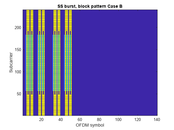
最后,绘制 SS 突发内容:
imagesc(abs(ssburst));
clim([0 4]);
axis xy;
xlabel('OFDM symbol');
ylabel('Subcarrier');
title('SS burst, block pattern Case B');

另请参阅
函数
nrPBCH|nrPBCHDMRS|nrPBCHDMRSIndices|nrPBCHIndices|nrSSS|nrSSSIndices|nrPSS|nrPSSIndices