NR Cell Search and MIB and SIB1 Recovery
This example demonstrates how to use 5G Toolbox™ to synchronize, demodulate, and decode a live gNodeB signal. The example decodes the MIB and the first of the system information blocks (SIB1). Decoding MIB and SIB1 requires a comprehensive receiver, capable of demodulating and decoding the majority of the downlink channels and signals.
Introduction
Before user equipment (UE) can communicate with the network, it must perform cell search and selection procedures and obtain initial system information. The first steps in that process are acquiring frame synchronization, finding out the cell identity and decoding the MIB and SIB1. This example shows how to perform these steps by using 5G Toolbox.
You can use this example with a captured waveform of I/Q samples or generate a local waveform containing a synchronization signal (SS) burst and SIB1 using nrWaveformGenerator. For locally generated waveforms, the example performs these steps:
Waveform generation: Configure and generate a synchronization signal burst carrying the MIB, CORESET 0, PDCCH and PDSCH carrying SIB1 by using the downlink waveform generator from 5G Toolbox. The transmitter can enhance the SNR of one SS block, but it does not perform beamforming. For more information on SSB beamforming, see NR SSB Beam Sweeping.
AWGN: Apply additive white Gaussian noise (AWGN) to the waveform.
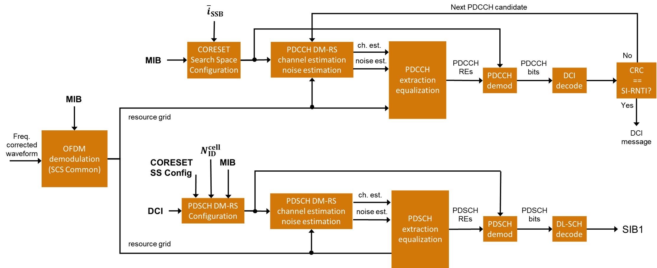
Receiver: Apply various synchronization and demodulation processes to the received waveform to establish the system frame number, cell identity and SSB, and decode the MIB. These provide the information required for blind decoding of downlink control information (DCI) in a PDCCH. The receiver uses DCI to configure the PDSCH demodulator, decode DL-SCH and finally recover the SIB1.
These figures show the processing steps inside the receiver.

Receiver Configuration
To synchronize and demodulate the received waveform, this information is needed:
The waveform sample rate to demodulate the received waveform.
The carrier center frequency to apply symbol phase compensation to the received waveform.
The minimum channel bandwidth to determine CORESET 0 frequency resources. TS 38.101-1 Table 5.3.5-1 [ 1 ] describes the channel bandwidths for each NR band.
The SS block pattern (Case A...E) to determine the subcarrier spacing of the SS/PBCH blocks. UE searches for SS block patterns based on the NR operating band. For more information, see TS 38.104 Tables 5.4.3.3-1 and 5.4.3.3-2 [ 2 ].
The number of SS/PBCH blocks in a burst (
 ) to calculate parameters of the PBCH DM-RS sequences and PBCH descrambling. These parameters depend on the SS/PBCH block index as described in TS 38.211 Sections 7.3.3.1 and 7.4.1.4.1 [ 3 ]. TS 38.213 Section 4.1 [ 5 ] describes the set of SS/PBCH blocks in a burst in each case. UE knows the value of
  based on the SS block pattern and the NR operating band.
loadFromFile = 0; % Set to 1 to load a captured waveform

if loadFromFile
    % Load captured waveform
    rx = load('capturedWaveformSIB1.mat');
    rxWaveform = rx.waveform;

    % Configure receiver sample rate (samples/second)
    sampleRate = rx.sampleRate;

    % Symbol phase compensation frequency. Specify the carrier center
    % frequency or set to 0 to disable symbol phase compensation
    fPhaseComp = rx.fPhaseComp; % Carrier center frequency (Hz)

    % Set the minimum channel bandwidth for the NR band required to
    % configure CORESET 0 in FR1 (See TS 38.101-1 Table 5.3.5-1)
    minChannelBW = rx.minChannelBW; % 5, 10, 40 MHz

    % Configure necessary burst parameters at the receiver. The SSB pattern
    % can be 'Case A','Case B','Case C' for FR1 or 'Case D','Case E' for
    % FR2. The maximum number of blocks L_max can be 4 or 8 for FR1 and 64
    % for FR2.
    refBurst.BlockPattern = rx.ssbBlockPattern;
    refBurst.L_max = rx.L_max;
else
    % Generate waveform containing SS burst and SIB1
    % Configure the cell identity
    config = struct();
    config.NCellID = 102;

    % Configure an SS burst
    config.BlockPattern = 'Case B';         % FR1: 'Case A','Case B','Case C'. FR2: 'Case D','Case E'
    config.TransmittedBlocks = ones(1,8);   % Bitmap of SS blocks transmitted
    config.SubcarrierSpacingCommon = 15;    % SIB1 subcarrier spacing in kHz (15 or 30 for FR1. 60 or 120 for FR2)
    config.EnableSIB1 = 1;                  % Set to 0 to disable SIB1

    % Set the minimum channel bandwidth for the NR band required to
    % configure CORESET 0 in FR1 (See TS 38.101-1 Table 5.3.5-1)
    config.MinChannelBW = 5; % 5, 10, 40 MHz

    % Introduce a beamforming gain by boosting the power (and therefore
    % SNR) of one SSB and associated SIB1 PDCCH and PDSCH
    boost = 6; % SNR boost in dB
    config.Power = zeros(size(config.TransmittedBlocks));
    config.Power(1) = boost; % boost the first SSB

    % Configure and generate a waveform containing an SS burst and SIB1
    wavegenConfig = hSIB1WaveformConfiguration(config);
    [txWaveform,waveInfo] = nrWaveformGenerator(wavegenConfig);
    txOfdmInfo = waveInfo.ResourceGrids(1).Info;

    % Add white Gaussian noise to the waveform. Note that the SNR only
    % applies to the boosted SSB / SIB1
    rng('default'); % Reset the random number generator
    SNRdB = 20; % SNR for AWGN
    rxWaveform = awgn(txWaveform,SNRdB-boost,-10*log10(double(txOfdmInfo.Nfft)));

    % Configure receiver
    % Sample rate
    sampleRate = txOfdmInfo.SampleRate;

    % Symbol phase compensation frequency (Hz). The function
    % nrWaveformGenerator does not apply symbol phase compensation to the
    % generated waveform.
    fPhaseComp = 0; % Carrier center frequency (Hz)

    % Minimum channel bandwidth (MHz)
    minChannelBW = config.MinChannelBW;

    % Configure necessary burst parameters at the receiver
    refBurst.BlockPattern = config.BlockPattern;
    refBurst.L_max = numel(config.TransmittedBlocks);
end

% Get OFDM information from configured burst and receiver parameters
nrbSSB = 20;
scsSSB = hSSBurstSubcarrierSpacing(refBurst.BlockPattern);
rxOfdmInfo = nrOFDMInfo(nrbSSB,scsSSB,'SampleRate',sampleRate);

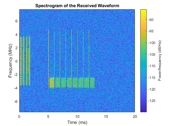
% Display spectrogram of received waveform
figure;
nfft = rxOfdmInfo.Nfft;
spectrogram(rxWaveform(:,1),ones(nfft,1),0,nfft,'centered',sampleRate,'yaxis','MinThreshold',-130);
title('Spectrogram of the Received Waveform')
PSS Search and Frequency Offset Correction
The receiver performs PSS search and coarse frequency offset estimation following these steps:
Frequency shift the received waveform with a candidate frequency offset. Candidate offsets are spaced half subcarrier apart. Use
searchBWto control the frequency offset search bandwidth.Correlate the frequency-shifted received waveform with each of the three possible PSS sequences (NID2) and extract the strongest correlation peak. The reference PSS sequences are centered in frequency. Therefore, the strongest correlation peak provides a measure of coarse frequency offset with respect to the center frequency of the carrier. The peak also indicates which of the three PSS (NID2) has been detected in the received waveform and the time instant of the best channel conditions.
Estimate frequency offsets below half subcarrier by correlating the cyclic prefix of each OFDM symbol in the SSB with the corresponding useful parts of the OFDM symbols. The phase of this correlation is proportional to the frequency offset in the waveform.
disp(' -- Frequency correction and timing estimation --')

% Specify the frequency offset search bandwidth in kHz
searchBW = 6*scsSSB;
[rxWave,freqOffset,NID2] = hSSBurstFrequencyCorrect(rxWaveform,refBurst.BlockPattern,sampleRate,searchBW);
disp([' Frequency offset: ' num2str(freqOffset,'%.0f') ' Hz'])
 -- Frequency correction and timing estimation --
 Frequency offset: -16 Hz

Time Synchronization and OFDM Demodulation
The receiver estimates the timing offset to the strongest SS block by using the reference PSS sequence detected in the frequency search process. After frequency offset correction, the receiver can assume that the center frequencies of the reference PSS and received waveform are aligned. Finally, the receiver OFDM demodulates the synchronized waveform and extracts the SS block.
% Create a reference grid for timing estimation using detected PSS. The PSS
% is placed in the second OFDM symbol of the reference grid to avoid the
% special CP length of the first OFDM symbol.
refGrid = zeros([nrbSSB*12 2]);
refGrid(nrPSSIndices,2) = nrPSS(NID2); % Second OFDM symbol for correct CP length

% Timing estimation. This is the timing offset to the OFDM symbol prior to
% the detected SSB due to the content of the reference grid
nSlot = 0;
timingOffset = nrTimingEstimate(rxWave,nrbSSB,scsSSB,nSlot,refGrid,'SampleRate',sampleRate);

% Synchronization, OFDM demodulation, and extraction of strongest SS block
rxGrid = nrOFDMDemodulate(rxWave(1+timingOffset:end,:),nrbSSB,scsSSB,nSlot,'SampleRate',sampleRate);
rxGrid = rxGrid(:,2:5,:);

% Display the timing offset in samples. As the symbol lengths are measured
% in FFT samples, scale the symbol lengths to account for the receiver
% sample rate.
srRatio = sampleRate/(scsSSB*1e3*rxOfdmInfo.Nfft);
firstSymbolLength = rxOfdmInfo.SymbolLengths(1)*srRatio;
str = sprintf(' Time offset to synchronization block: %%.0f samples (%%.%.0ff ms) \n',floor(log10(sampleRate))-3);
fprintf(str,timingOffset+firstSymbolLength,(timingOffset+firstSymbolLength)/sampleRate*1e3);
Time offset to synchronization block: 2200 samples (0.1432 ms)
SSS Search
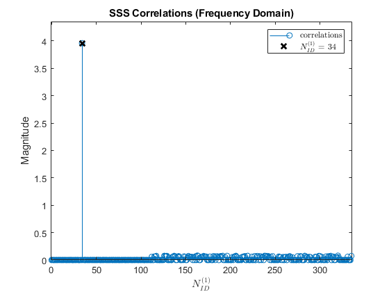
The receiver extracts the resource elements associated to the SSS from the received grid and correlates them with each possible SSS sequence generated locally. The indices of the strongest PSS and SSS sequences combined give the physical layer cell identity, which is required for PBCH DM-RS and PBCH processing.
% Extract the received SSS symbols from the SS/PBCH block
sssIndices = nrSSSIndices;
sssRx = nrExtractResources(sssIndices,rxGrid);

% Correlate received SSS symbols with each possible SSS sequence
sssEst = zeros(1,336);
for NID1 = 0:335

    ncellid = (3*NID1) + NID2;
    sssRef = nrSSS(ncellid);
    sssEst(NID1+1) = sum(abs(mean(sssRx .* conj(sssRef),1)).^2);

end

% Plot SSS correlations
figure;
stem(0:335,sssEst,'o');
title('SSS Correlations (Frequency Domain)');
xlabel('$N_{ID}^{(1)}$','Interpreter','latex');
ylabel('Magnitude');
axis([-1 336 0 max(sssEst)*1.1]);

% Determine NID1 by finding the strongest correlation
NID1 = find(sssEst==max(sssEst)) - 1;

% Plot selected NID1
hold on;
plot(NID1,max(sssEst),'kx','LineWidth',2,'MarkerSize',8);
legend(["correlations" "$N_{ID}^{(1)}$ = " + num2str(NID1)],'Interpreter','latex');

% Form overall cell identity from estimated NID1 and NID2
ncellid = (3*NID1) + NID2;

disp([' Cell identity: ' num2str(ncellid)])
Cell identity: 102
PBCH DM-RS search
In a process similar to SSS search, the receiver constructs each possible PBCH DM-RS sequence and performs channel and noise estimation. The index of the PBCH DM-RS with the best SNR determines the LSBs of the SS/PBCH block index required for PBCH scrambling initialization.
% Calculate PBCH DM-RS indices
dmrsIndices = nrPBCHDMRSIndices(ncellid);

% Perform channel estimation using DM-RS symbols for each possible DM-RS
% sequence and estimate the SNR
dmrsEst = zeros(1,8);
for ibar_SSB = 0:7

    refGrid = zeros([240 4]);
    refGrid(dmrsIndices) = nrPBCHDMRS(ncellid,ibar_SSB);
    [hest,nest] = nrChannelEstimate(rxGrid,refGrid,'AveragingWindow',[0 1]);
    dmrsEst(ibar_SSB+1) = 10*log10(mean(abs(hest(:).^2)) / nest);

end

% Plot PBCH DM-RS SNRs
figure;
stem(0:7,dmrsEst,'o');
title('PBCH DM-RS SNR Estimates');
xlabel('$\overline{i}_{SSB}$','Interpreter','latex');
xticks(0:7);
ylabel('Estimated SNR (dB)');
axis([-1 8 min(dmrsEst)-1 max(dmrsEst)+1]);

% Record ibar_SSB for the highest SNR
ibar_SSB = find(dmrsEst==max(dmrsEst)) - 1;

% Plot selected ibar_SSB
hold on;
plot(ibar_SSB,max(dmrsEst),'kx','LineWidth',2,'MarkerSize',8);
legend(["SNRs" "$\overline{i}_{SSB}$ = " + num2str(ibar_SSB)],'Interpreter','latex');

Channel Estimation using PBCH DM-RS and SSS
The receiver estimates the channel for the entire SS/PBCH block using the SSS and PBCH DM-RS detected in previous steps. An estimate of the additive noise on the PBCH DM-RS / SSS is also performed.
refGrid = zeros([nrbSSB*12 4]);
refGrid(dmrsIndices) = nrPBCHDMRS(ncellid,ibar_SSB);
refGrid(sssIndices) = nrSSS(ncellid);
[hest,nVar,hestInfo] = nrChannelEstimate(rxGrid,refGrid,'AveragingWindow',[0 1]);
PBCH Demodulation
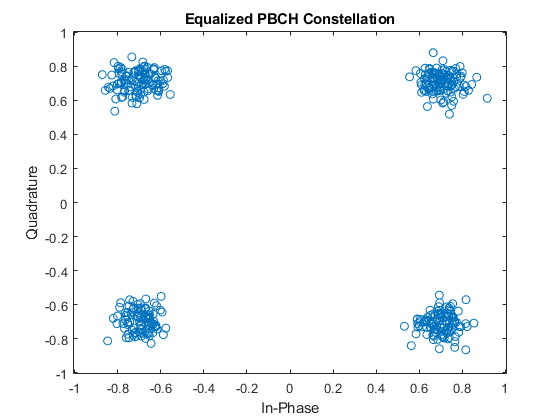
The receiver uses the cell identity to determine and extract the resource elements associated with the PBCH from the received grid. In addition, the receiver uses the channel and noise estimates to perform MMSE equalization. The equalized PBCH symbols are then demodulated and descrambled to give bit estimates for the coded BCH block.
disp(' -- PBCH demodulation and BCH decoding -- ')

% Extract the received PBCH symbols from the SS/PBCH block
[pbchIndices,pbchIndicesInfo] = nrPBCHIndices(ncellid);
pbchRx = nrExtractResources(pbchIndices,rxGrid);

% Configure 'v' for PBCH scrambling according to TS 38.211 Section 7.3.3.1
% 'v' is also the 2 LSBs of the SS/PBCH block index for L_max=4, or the 3
% LSBs for L_max=8 or 64.
if refBurst.L_max == 4
    v = mod(ibar_SSB,4);
else
    v = ibar_SSB;
end
ssbIndex = v;

% PBCH equalization and CSI calculation
pbchHest = nrExtractResources(pbchIndices,hest);
[pbchEq,csi] = nrEqualizeMMSE(pbchRx,pbchHest,nVar);
Qm = pbchIndicesInfo.G / pbchIndicesInfo.Gd;
csi = repmat(csi.',Qm,1);
csi = reshape(csi,[],1);

% Plot received PBCH constellation after equalization
figure;
plot(pbchEq,'o');
xlabel('In-Phase'); ylabel('Quadrature')
title('Equalized PBCH Constellation');
m = max(abs([real(pbchEq(:)); imag(pbchEq(:))])) * 1.1;
axis([-m m -m m]);

% PBCH demodulation
pbchBits = nrPBCHDecode(pbchEq,ncellid,v,nVar);

% Calculate RMS PBCH EVM in %
pbchRef = nrPBCH(pbchBits<0,ncellid,v);
pbchEVMrms = nrEVM(pbchEq,pbchRef)*100;

% Display calculated EVM
disp([' PBCH RMS EVM: ' num2str(pbchEVMrms,'%0.3f') '%']);
 -- PBCH demodulation and BCH decoding --
 PBCH RMS EVM: 12.432%
BCH Decoding
The receiver weights BCH bit estimates with channel state information (CSI) from the MMSE equalizer and decodes the BCH. BCH decoding consists of rate recovery, polar decoding, CRC decoding, descrambling, and separating the 24 BCH transport block bits from the 8 additional timing-related payload bits.
% Apply CSI
pbchBits = pbchBits .* csi;

% Perform BCH decoding including rate recovery, polar decoding, and CRC
% decoding. PBCH descrambling and separation of the BCH transport block
% bits 'trblk' from 8 additional payload bits A...A+7 is also performed:
%   A ... A+3: 4 LSBs of system frame number
%         A+4: half frame number
% A+5 ... A+7: for L_max=64, 3 MSBs of the SS/PBCH block index
%              for L_max=4 or 8, A+5 is the MSB of subcarrier offset k_SSB
polarListLength = 8;
[~,crcBCH,trblk,sfn4lsb,nHalfFrame,msbidxoffset] = ...
    nrBCHDecode(pbchBits,polarListLength,refBurst.L_max,ncellid);

% Display the BCH CRC
disp([' BCH CRC: ' num2str(crcBCH)]);

% Stop processing MIB and SIB1 if BCH was received with errors
if crcBCH
    disp(' BCH CRC is not zero.');
    return
end

% Use 'msbidxoffset' value to set bits of 'k_SSB' or 'ssbIndex', depending
% on the number of SS/PBCH blocks in the burst
if (refBurst.L_max==64)
    ssbIndex = ssbIndex + (bit2int(msbidxoffset,3) * 8);
    k_SSB = 0;
else
    k_SSB = msbidxoffset * 16;
end

% Displaying the SSB index
disp([' SSB index: ' num2str(ssbIndex)]);
 BCH CRC: 0
 SSB index: 0
MIB and BCH Parsing
The example parses the 24 decoded BCH transport block bits into a MIB message and creates the initialSystemInfo structure with initial system information. This process includes reconstituting the 10-bit system frame number (SFN) NFrame from the 6 MSBs in the MIB and the 4 LSBs in the PBCH payload bits. It also includes incorporating the MSB of the subcarrier offset k_SSB from the PBCH payload bits in the case of L_max=4 or 8 SS/PBCH blocks per burst.
% Parse the last 23 decoded BCH transport block bits into a MIB message.
% The BCH transport block 'trblk' is the RRC message BCCH-BCH-Message,
% consisting of a leading 0 bit and 23 bits corresponding to the MIB. The
% leading bit signals the message type transmitted (MIB or empty sequence).

mib = fromBits(MIB,trblk(2:end)); % Do not parse leading bit

% Create a structure containing complete initial system information
initialSystemInfo = initSystemInfo(mib,sfn4lsb,k_SSB,refBurst.L_max);

% Display the MIB structure
disp(' BCH/MIB Content:')
disp(initialSystemInfo);

% Check if a CORESET for Type0-PDCCH common search space (CSS) is present,
% according to TS 38.213 Section 4.1
if ~isCORESET0Present(refBurst.BlockPattern,initialSystemInfo.k_SSB)
    fprintf('CORESET 0 is not present (k_SSB > k_SSB_max).\n');
    return
end
 BCH/MIB Content:
                     NFrame: 0
    SubcarrierSpacingCommon: 15
                      k_SSB: 0
          DMRSTypeAPosition: 3
            PDCCHConfigSIB1: [1×1 struct]
                 CellBarred: 0
       IntraFreqReselection: 0
OFDM Demodulation on Full Bandwidth
Once the MIB is recovered, the receiver uses common subcarrier spacing and a bandwidth supporting CORESET 0 to OFDM demodulate the frame containing the detected SS block. The receiver determines the CORESET 0 frequency resources in common numerology through an offset from the location of the SSB detected and a bandwidth specified in TS 38.213 Section 13 Tables 13-1 through 13-10 [ 5 ]. The frequency correction process aligned the center of the OFDM resource grid with the center frequency of the SS burst. However, these centers are not necessarily aligned with the center frequency of CORESET 0. This figure shows the relationship between the SSB, CORESET 0 frequency resources and associated PDCCH monitoring occasions.
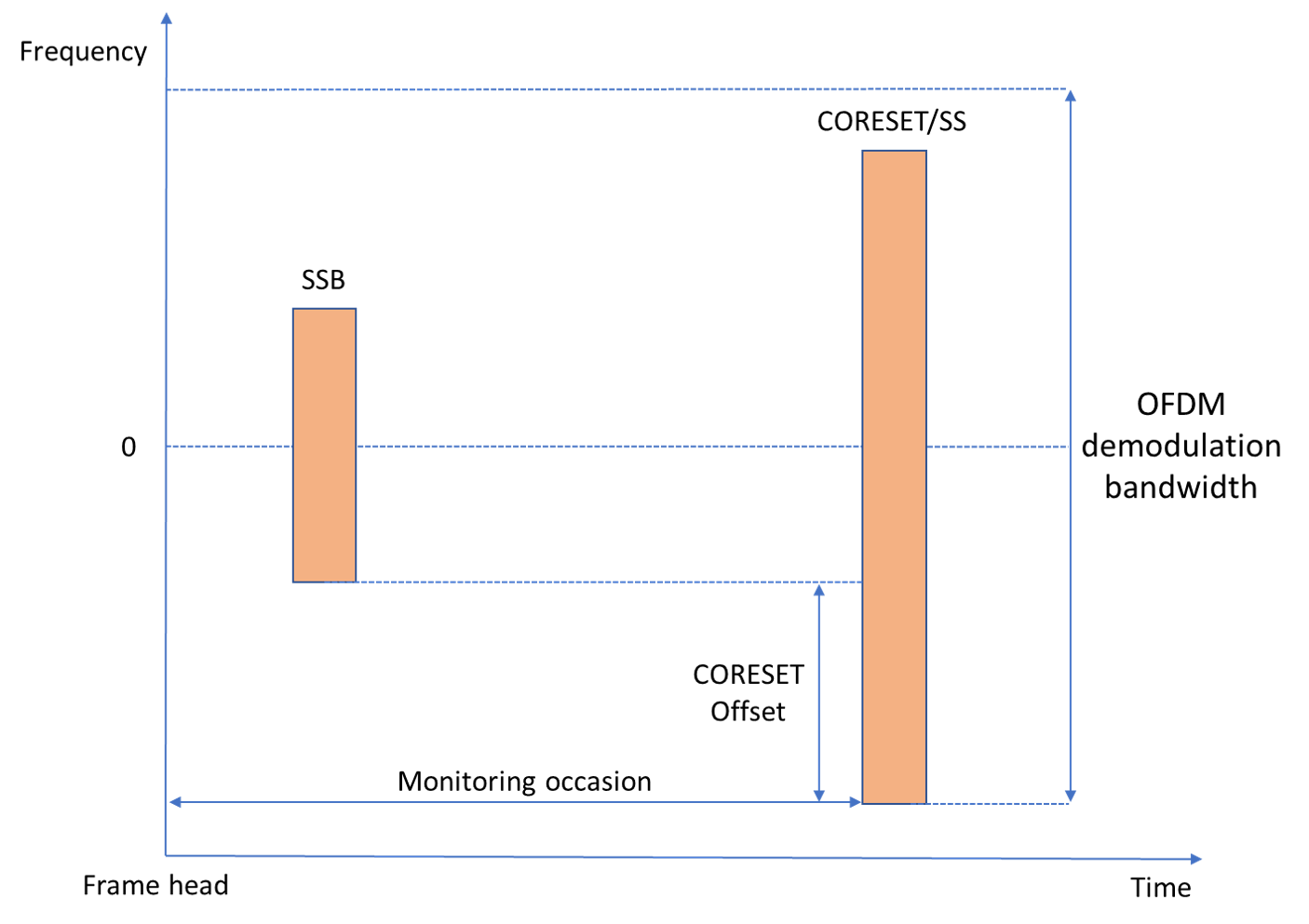
Unlike the SS burst, control and data channels must be aligned in frequency with their common resource block (CRB) raster. The value of KSSB indicates the frequency offset of the SSB from that CRB raster. As the frequency correction process centered the SSB in frequency, apply a frequency shift determined by k_SSB to align data and control channels with their CRB before OFDM demodulation
k_SSB = initialSystemInfo.k_SSB;
scsCommon = initialSystemInfo.SubcarrierSpacingCommon;
scsKSSB = kSSBSubcarrierSpacing(scsCommon);
kFreqShift = k_SSB*scsKSSB*1e3;
rxWave = rxWave.*exp(1i*2*pi*kFreqShift*(0:length(rxWave)-1)'/sampleRate);

% Adjust the symbol phase compensation frequency with the frequency shift
% introduced.
fPhaseComp = fPhaseComp - kFreqShift;
Adjust timing offset to the frame origin of the first frame that can schedule an SS/PBCH block. If the frame offset is negative, the first frame is incomplete. Add leading zeros to the waveform to align the waveform to that frame.
[frameOffset,nLeadingFrames] = hTimingOffsetToFirstFrame(timingOffset,refBurst,ssbIndex,nHalfFrame,sampleRate);

% Add leading zeros
zeroPadding = zeros(-min(frameOffset,0),size(rxWave,2));
rxWave = [zeroPadding; rxWave(1+max(frameOffset,0):end,:)];

% Determine the number of resource blocks and subcarrier spacing for OFDM
% demodulation of CORESET 0.
nrb = hCORESET0DemodulationBandwidth(initialSystemInfo,scsSSB,minChannelBW);

if sampleRate < nrb*12*scsCommon*1e3
    disp(['SIB1 recovery cannot continue. CORESET 0 resources are beyond '...
          'the frequency limits of the received waveform for the sampling rate configured.']);
    return;
end

% OFDM demodulate received waveform with common subcarrier spacing
nSlot = 0;
rxGrid = nrOFDMDemodulate(rxWave, nrb, scsCommon, nSlot,...
                         'SampleRate',sampleRate,'CarrierFrequency',fPhaseComp);

% Display OFDM resource grid and highlight strongest SS block
plotResourceGrid(rxGrid,refBurst,initialSystemInfo,nLeadingFrames,ssbIndex,nHalfFrame)

Demodulation of PDCCH and Downlink Control Information Decoding
To blindly search for system information DCI messages in CORESET/SS, the receiver performs these steps:
Determination of PDCCH monitoring occasions and extraction of the OFDM resource grid containing control information.
Configuration of CORESET 0, Search spaces and PDCCH.
Blind search for Format 1_0 DCI messages.
The receiver determines the PDCCH monitoring occasions through a slot and OFDM symbol offset from the location of the SS block detected, as described in TS 38.213 Tables 13-11 and 13-12 [ 5 ]. The receiver adjusts the system frame number to account for the new synchronization time to the first frame available in the waveform.
initialSystemInfo.NFrame = mod(initialSystemInfo.NFrame - nLeadingFrames,1024);
numRxSym = size(rxGrid,2);
[csetSubcarriers,monSlots,monSlotsSym,ssStartSym] = hPDCCH0MonitoringResources(initialSystemInfo,scsSSB,minChannelBW,ssbIndex,numRxSym);

% Check if search space is beyond end of waveform
if isempty(monSlotsSym)
    disp('Search space slot is beyond end of waveform.');
    return;
end

% Extract slots containing strongest PDCCH from the received grid
rxMonSlotGrid = rxGrid(csetSubcarriers,monSlotsSym,:);
Configure CORESET, search space, and other PDCCH parameters. CORESET resources and search spaces are configured according to TS 38.213 Section 13 Tables 13-1 through 13-15 [ 5 ]. CCE-to-REG interleaved mapping parameters (REGBundleSize = 6, InterleaverSize = 2, and ShiftIndex = NCellID) are described in TS 38.211 Section 7.3.2.2 [ 3 ]. For CORESET 0, the BWP is the size of the CORESET as described in TS 38.212 Section 7.3.1.0 [ 4 ]. The PDCCH scrambling parameters are nRNTI = 0 and nID = NCellID as described in TS 38.211 Section 7.3.2.3 [ 3 ].
scsPair = [scsSSB scsCommon];
[pdcch,csetPattern] = hPDCCH0Configuration(ssbIndex,initialSystemInfo,scsPair,ncellid,minChannelBW);

% Configure the carrier to span the BWP (CORESET 0)
carrier = hCarrierConfigSIB1(ncellid,initialSystemInfo,pdcch);
Search for DCI messages. UE decodes the received PDCCH symbols blindly by monitoring all PDCCH candidates for every aggregation level using the SI-RNTI to identify the right candidate (or instance).
% Specify DCI message with Format 1_0 scrambled with SI-RNTI (TS 38.212
% Section 7.3.1.2.1)
dci = DCIFormat1_0_SIRNTI(pdcch.NSizeBWP);

disp(' -- Downlink control information message search in PDCCH -- ');

symbolsPerSlot = 14;
siRNTI = 65535; % TS 38.321 Table 7.1-1
dciCRC = true;
mSlotIdx = 0;
% Loop over all monitoring slots
while (mSlotIdx < length(monSlots)) && dciCRC

    % Update slot number to next monitoring slot
    carrier.NSlot = monSlots(mSlotIdx+1);

    % Get PDCCH candidates according to TS 38.213 Section 10.1
    [pdcchInd,pdcchDmrsSym,pdcchDmrsInd] = nrPDCCHSpace(carrier,pdcch);

    % Extract resource grid for this monitoring slot and normalize
    rxSlotGrid = rxMonSlotGrid(:,(1:symbolsPerSlot) + symbolsPerSlot*mSlotIdx,:);
    rxSlotGrid = rxSlotGrid/max(abs(rxSlotGrid(:)));

    % Proceed to blind decoding only if the PDCCH REs are not zero.
    notZero = any(cellfun(@(x)any(rxSlotGrid(x),'all'),pdcchInd));

    % Loop over all supported aggregation levels
    aLevIdx = 1;
    while (aLevIdx <= 5) && dciCRC && notZero
        % Loop over all candidates at each aggregation level in SS
        cIdx = 1;
        numCandidatesAL = pdcch.SearchSpace.NumCandidates(aLevIdx);
        while (cIdx <= numCandidatesAL) && dciCRC
            % Channel estimation using PDCCH DM-RS
            [hest,nVar,pdcchHestInfo] = nrChannelEstimate(rxSlotGrid,pdcchDmrsInd{aLevIdx}(:,cIdx),pdcchDmrsSym{aLevIdx}(:,cIdx));

            % Equalization and demodulation of PDCCH symbols
            [pdcchRxSym,pdcchHest] = nrExtractResources(pdcchInd{aLevIdx}(:,cIdx),rxSlotGrid,hest);
            pdcchEqSym = nrEqualizeMMSE(pdcchRxSym,pdcchHest,nVar);
            dcicw = nrPDCCHDecode(pdcchEqSym,pdcch.DMRSScramblingID,pdcch.RNTI,nVar);

            % DCI message decoding
            polarListLength = 8;
            [dcibits,dciCRC] = nrDCIDecode(dcicw,dci.Width,polarListLength,siRNTI);

            if dciCRC == 0
                disp([' Decoded PDCCH candidate #' num2str(cIdx) ' at aggregation level ' num2str(2^(aLevIdx-1))])
            end
            cIdx = cIdx + 1;
        end
        aLevIdx = aLevIdx+1;
    end
    mSlotIdx = mSlotIdx+1;
end
mSlotIdx = mSlotIdx-1;
monSlotsSym = monSlotsSym(mSlotIdx*symbolsPerSlot + (1:symbolsPerSlot));

% Highlight CORESET 0/SS occasions in resource grid
highlightCORESET0SS(csetSubcarriers,monSlots,monSlots(mSlotIdx+1),pdcch,dciCRC)

if dciCRC
    disp(' DCI decoding failed.');
    return
end

% Calculate RMS PDCCH EVM in %
pdcchRef = nrPDCCH(double(dcicw<0),pdcch.DMRSScramblingID,pdcch.RNTI);
pdcchEVMrms = nrEVM(pdcchEqSym,pdcchRef)*100;

% Display calculated EVM
disp([' PDCCH RMS EVM: ' num2str(pdcchEVMrms,'%0.3f') '%']);
disp([' PDCCH CRC: ' num2str(dciCRC)]);

% Plot received PDCCH constellation after equalization
figure;
plot(pdcchEqSym,'o');
xlabel('In-Phase'); ylabel('Quadrature')
title('Equalized PDCCH Constellation');
m = max(abs([real(pdcchEqSym(:)); imag(pdcchEqSym(:))])) * 1.1;
axis([-m m -m m]);
 -- Downlink control information message search in PDCCH --
 Decoded PDCCH candidate #1 at aggregation level 8
 PDCCH RMS EVM: 12.339%
 PDCCH CRC: 0


Demodulation of PDSCH, Decoding of DL-SCH and SIB1 Extraction
To recover the first system information block, the receiver performs these steps:
Determination of PDSCH configuration using cell ID, BCH information, and DCI
Channel estimation, equalization and demodulation of PDSCH symbols
Decoding of DL-SCH and SIB1 extraction
% Build DCI message structure
dci = fromBits(dci,dcibits);

% Get PDSCH configuration from cell ID, BCH information, and DCI
[pdsch,K0] = hSIB1PDSCHConfiguration(dci,pdcch.NSizeBWP,initialSystemInfo.DMRSTypeAPosition,csetPattern);

% For CORESET pattern 2, the gNodeB can allocate PDSCH in the next slot,
% which is indicated by the slot offset K_0 signaled by DCI. For more
% information, see TS 38.214 Table 5.1.2.1.1-4.
carrier.NSlot = carrier.NSlot + K0;
monSlotsSym = monSlotsSym+symbolsPerSlot*K0;

if K0 > 0
    % Display the OFDM grid of the slot containing associated PDSCH
    figure;
    imagesc(abs(rxGrid(csetSubcarriers,monSlotsSym,1))); axis xy
    xlabel('OFDM symbol');
    ylabel('subcarrier');
    title('Slot Containing PDSCH (Slot Offset K_0 = 1)');
end

% PDSCH channel estimation and equalization using PDSCH DM-RS
pdschDmrsIndices = nrPDSCHDMRSIndices(carrier,pdsch);
pdschDmrsSymbols = nrPDSCHDMRS(carrier,pdsch);
To compensate for the negative effects of a carrier frequency mismatch in symbol phase compensation and channel estimation, the receiver OFDM demodulates the waveform with a set of carrier frequencies over a search bandwidth around fPhaseComp. The search finishes when DL-SCH decoding succeeds or the last frequency has been reached. The minimum search bandwidths that produce equal symbol phase compensation are 1920, 3840, 7680, and 15360 kHz for common subcarrier spacings 15, 30, 60, and 120 kHz, respectively. Increase the search bandwidth up to these values when SIB1 decoding fails and the equalized PDSCH symbols result in a heavily distorted and rotated constellation.
disp(' -- PDSCH demodulation and DL-SCH decoding -- ')

mu = log2(scsCommon/15);
bw = 2^mu*100;   % Search bandwidth (kHz)
freqStep = 2^mu; % Frequency step (kHz)
freqSearch = -bw/2:freqStep:bw/2-freqStep;
[~,fSearchIdx] = sort(abs(freqSearch)); % Sort frequencies from center
freqSearch = freqSearch(fSearchIdx);

for fpc = fPhaseComp + 1e3*freqSearch

    % OFDM demodulate received waveform
    nSlot = 0;
    rxGrid = nrOFDMDemodulate(rxWave, nrb, scsCommon, nSlot,...
                                'SampleRate',sampleRate,'CarrierFrequency',fpc);

    % Extract monitoring slot from the received grid
    rxSlotGrid = rxGrid(csetSubcarriers,monSlotsSym,:);
    rxSlotGrid = rxSlotGrid/max(abs(rxSlotGrid(:))); % Normalization of received RE magnitude

    % Channel estimation and equalization of PDSCH symbols
    [hest,nVar,pdschHestInfo] = nrChannelEstimate(rxSlotGrid,pdschDmrsIndices,pdschDmrsSymbols);
    [pdschIndices,pdschIndicesInfo] = nrPDSCHIndices(carrier,pdsch);
    [pdschRxSym,pdschHest] = nrExtractResources(pdschIndices,rxSlotGrid,hest);
    pdschEqSym = nrEqualizeMMSE(pdschRxSym,pdschHest,nVar);

    % PDSCH demodulation
    cw = nrPDSCHDecode(carrier,pdsch,pdschEqSym,nVar);

    % Create and configure DL-SCH decoder with target code rate and
    % transport block size
    decodeDLSCH = nrDLSCHDecoder;
    decodeDLSCH.LDPCDecodingAlgorithm = 'Normalized min-sum';
    Xoh_PDSCH = 0; % TS 38.214 Section 5.1.3.2
    mcsTables = nrPDSCHMCSTables;
    qam64Table = mcsTables.QAM64Table; % TS 38.214 Table 5.1.3.1-1
    tcr = qam64Table.TargetCodeRate(qam64Table.MCSIndex==dci.ModulationCoding);
    NREPerPRB = pdschIndicesInfo.NREPerPRB;
    tbsLength = nrTBS(pdsch.Modulation,pdsch.NumLayers,length(pdsch.PRBSet),NREPerPRB,tcr,Xoh_PDSCH);
    decodeDLSCH.TransportBlockLength = tbsLength;
    decodeDLSCH.TargetCodeRate = tcr;

    % Decode DL-SCH
    [sib1bits,sib1CRC] = decodeDLSCH(cw,pdsch.Modulation,pdsch.NumLayers,dci.RedundancyVersion);

    if sib1CRC == 0
        break;
    end

end

% Highlight PDSCH and PDSCH DM-RS in resource grid.
pdcch.AggregationLevel = 2^(aLevIdx-2);
pdcch.AllocatedCandidate = cIdx-1;
plotResourceGridSIB1(rxSlotGrid,carrier,pdcch,pdsch,tcr,K0);

% Plot received PDSCH constellation after equalization
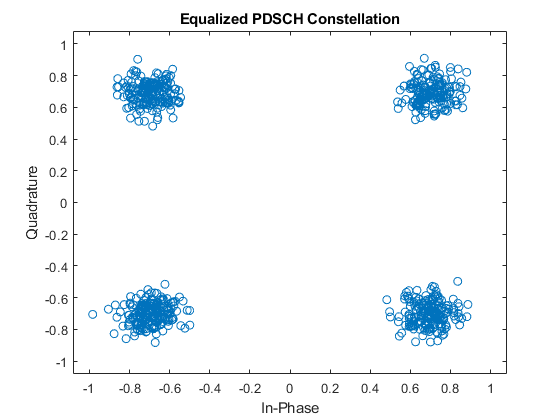
figure;
plot(pdschEqSym,'o');
xlabel('In-Phase'); ylabel('Quadrature')
title('Equalized PDSCH Constellation');
m = max(abs([real(pdschEqSym(:)); imag(pdschEqSym(:))])) * 1.1;
axis([-m m -m m]);

% Calculate RMS PDSCH EVM in %, including normalization of PDSCH symbols
% for any offset between DM-RS and PDSCH power
pdschRef = nrPDSCH(carrier,pdsch,double(cw{1}<0));
pdschEVMrms = nrEVM(pdschEqSym/sqrt(var(pdschEqSym)),pdschRef)*100;

% Display PDSCH EVM and DL-SCH CRC
disp([' PDSCH RMS EVM: ' num2str(pdschEVMrms,'%0.3f') '%']);
disp([' PDSCH CRC: ' num2str(sib1CRC)]);

if sib1CRC == 0
    disp(' SIB1 decoding succeeded.');
else
    disp(' SIB1 decoding failed.');
end
 -- PDSCH demodulation and DL-SCH decoding --
 PDSCH RMS EVM: 10.277%
 PDSCH CRC: 0
 SIB1 decoding succeeded.
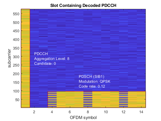
References
3GPP TS 38.101-1. "NR; User Equipment (UE) radio transmission and reception; Part 1: Range 1 Standalone" 3rd Generation Partnership Project; Technical Specification Group Radio Access Network.
3GPP TS 38.104. "NR; Base Station (BS) radio transmission and reception." 3rd Generation Partnership Project; Technical Specification Group Radio Access Network.
3GPP TS 38.211. "NR; Physical channels and modulation." 3rd Generation Partnership Project; Technical Specification Group Radio Access Network.
3GPP TS 38.212. "NR; Multiplexing and channel coding." 3rd Generation Partnership Project; Technical Specification Group Radio Access Network.
3GPP TS 38.213. "NR; Physical layer procedures for control." 3rd Generation Partnership Project; Technical Specification Group Radio Access Network.
3GPP TS 38.214. "NR; Physical layer procedures for data." 3rd Generation Partnership Project; Technical Specification Group Radio Access Network.
3GPP TS 38.321. "NR; Medium Access Control (MAC) protocol specification." 3rd Generation Partnership Project; Technical Specification Group Radio Access Network.
Local functions
function present = isCORESET0Present(ssbBlockPattern,kSSB)

    switch ssbBlockPattern
        case {'Case A','Case B','Case C'} % FR1
            kssb_max = 23;
        case {'Case D','Case E'} % FR2
            kssb_max = 11;
    end
    if (kSSB <= kssb_max)
        present = true;
    else
        present = false;
    end

end

function [timingOffset,nLeadingFrames] = hTimingOffsetToFirstFrame(offset,burst,ssbIdx,nHalfFrame,sampleRate)

    % As the symbol lengths are measured in FFT samples, scale the symbol
    % lengths to account for the receiver sample rate. Non-integer delays
    % are approximated at the end of the process.
    scs = hSSBurstSubcarrierSpacing(burst.BlockPattern);
    ofdmInfo = nrOFDMInfo(1,scs,'SampleRate',sampleRate); % smallest FFT size for SCS-SR
    srRatio = sampleRate/(scs*1e3*ofdmInfo.Nfft);
    symbolLengths = ofdmInfo.SymbolLengths*srRatio;

    % Adjust timing offset to the start of the SS block. This step removes
    % the extra offset introduced in the reference grid during PSS search,
    % which contained the PSS in the second OFDM symbol.
    offset = offset + symbolLengths(1);

    % Timing offset is adjusted so that the received grid starts at the
    % frame head i.e. adjust the timing offset for the difference between
    % the first symbol of the strongest SSB, and the start of the frame
    burstStartSymbols = hSSBurstStartSymbols(burst.BlockPattern,burst.L_max); % Start symbols in SSB numerology
    ssbFirstSym = burstStartSymbols(ssbIdx+1); % 0-based

    % Adjust for whole subframes
    symbolsPerSubframe = length(symbolLengths);
    subframeOffset = floor(ssbFirstSym/symbolsPerSubframe);
    samplesPerSubframe = sum(symbolLengths);
    timingOffset = offset - (subframeOffset*samplesPerSubframe);

    % Adjust for remaining OFDM symbols
    symbolOffset = mod(ssbFirstSym,symbolsPerSubframe);
    timingOffset = timingOffset - sum(symbolLengths(1:symbolOffset));

    % The first OFDM symbol of the SSB is defined with respect to the
    % half-frame where it is transmitted. Adjust for half-frame offset
    timingOffset = timingOffset - nHalfFrame*5*samplesPerSubframe;

    % Adjust offset to the first frame in the waveform that is scheduled
    % for SSB transmission.
    repetitions = ceil(timingOffset/(20*samplesPerSubframe));
    timingOffset = round(timingOffset - repetitions*20*samplesPerSubframe);

    % Calculate the number of leading frames before the detected one
    nLeadingFrames = 2*repetitions;

end

function initSystemInfo = initSystemInfo(mib,sfn4lsb,k_SSB,L_max)

    % Create set of subcarrier spacings signaled by the 7th bit of the
    % decoded MIB, the set is different for FR1 (L_max=4 or 8) and FR2
    % (L_max=64)
    if (L_max==64)
        scsCommon = [60 120];
    else
        scsCommon = [15 30];
    end

    initSystemInfo = struct();
    initSystemInfo.NFrame = mib.systemFrameNumber*2^4 + bit2int(sfn4lsb,4);
    initSystemInfo.SubcarrierSpacingCommon = scsCommon(mib.subCarrierSpacingCommon + 1);
    initSystemInfo.k_SSB = k_SSB + mib.ssb_SubcarrierOffset;
    initSystemInfo.DMRSTypeAPosition = 2 + mib.dmrs_TypeA_Position;
    initSystemInfo.PDCCHConfigSIB1 = info(mib.pdcch_ConfigSIB1);
    initSystemInfo.CellBarred = mib.cellBarred;
    initSystemInfo.IntraFreqReselection = mib.intraFreqReselection;

end

function nrb = hCORESET0DemodulationBandwidth(sysInfo,scsSSB,minChannelBW)

    % Determine the OFDM demodulation bandwidth from CORESET 0 bandwidth
    cset0Idx = sysInfo.PDCCHConfigSIB1.controlResourceSetZero;
    scsCommon = sysInfo.SubcarrierSpacingCommon;
    scsPair = [scsSSB scsCommon];
    [csetNRB,~,csetFreqOffset] = hCORESET0Resources(cset0Idx,scsPair,minChannelBW,sysInfo.k_SSB);

    % Calculate a suitable bandwidth in RB that includes CORESET 0 in
    % received waveform.
    c0 = csetFreqOffset + 10*scsSSB/scsCommon;  % CORESET frequency offset from carrier center
    nrb = 2*max(c0,csetNRB-c0)+2;               % Number of RB to cover CORESET 0

end

function [k,slots,slotSymbols,ssStartSym] = hPDCCH0MonitoringResources(systemInfo,scsSSB,minChannelBW,ssbIndex,numRxSym)

    cset0Idx = systemInfo.PDCCHConfigSIB1.controlResourceSetZero;
    scsCommon = systemInfo.SubcarrierSpacingCommon;
    scsPair = [scsSSB scsCommon];
    k_SSB = systemInfo.k_SSB;
    [c0NRB,c0Duration,c0FreqOffset,c0Pattern] = hCORESET0Resources(cset0Idx,scsPair,minChannelBW,k_SSB);

    ssIdx = systemInfo.PDCCHConfigSIB1.searchSpaceZero;
    [ssSlot,ssStartSym,isOccasion] = hPDCCH0MonitoringOccasions(ssIdx,ssbIndex,scsPair,c0Pattern,c0Duration,systemInfo.NFrame);

    % PDCCH monitoring occasions associated to different SS blocks can be
    % in different frames. If there are no monitoring occasions in this
    % frame, there must be one in the next one. Adjust the slots associated
    % to the search space by one frame if needed.
    slotsPerFrame = 10*scsCommon/15;
    ssSlot = ssSlot + (~isOccasion)*slotsPerFrame;

    % For FR1, UE monitors PDCCH in the Type0-PDCCH CSS over two consecutive
    % slots for CORESET pattern 1
    monSlotsPerPeriod = 1 + (c0Pattern==1);

    % Calculate 1-based subscripts of the subcarriers and OFDM symbols for
    % the slots containing the PDCCH0 associated to the detected SS block
    % in this and subsequent 2-frame blocks
    nrb = hCORESET0DemodulationBandwidth(systemInfo,scsSSB,minChannelBW);
    k = 12*(nrb-20*scsSSB/scsCommon)/2 - c0FreqOffset*12 + (1:c0NRB*12);

    symbolsPerSlot = 14;
    numRxSlots = ceil(numRxSym/symbolsPerSlot);
    slots = ssSlot + (0:monSlotsPerPeriod-1)' + (0:2*slotsPerFrame:(numRxSlots-ssSlot-1));
    slots = slots(:)';
    slotSymbols = slots*symbolsPerSlot + (1:symbolsPerSlot)';
    slotSymbols = slotSymbols(:)';

    % Remove monitoring symbols exceeding waveform limits
    slotSymbols(slotSymbols>numRxSym) = [];

    % Calculate the monitoring slots after removing symbols
    slots = (slotSymbols(1:symbolsPerSlot:end)-1)/symbolsPerSlot;

end

function scsKSSB = kSSBSubcarrierSpacing(scsCommon)
% Subcarrier spacing of k_SSB, as defined in TS 38.211 Section 7.4.3.1

    if scsCommon > 30  % FR2
        scsKSSB = scsCommon;
    else
        scsKSSB = 15;
    end

end

function c = hCarrierConfigSIB1(ncellid,initSystemInfo,pdcch)

    c = nrCarrierConfig;
    c.SubcarrierSpacing = initSystemInfo.SubcarrierSpacingCommon;
    c.NStartGrid = pdcch.NStartBWP;
    c.NSizeGrid = pdcch.NSizeBWP;
    c.NSlot = pdcch.SearchSpace.SlotPeriodAndOffset(2);
    c.NFrame = initSystemInfo.NFrame;
    c.NCellID = ncellid;

end

function plotResourceGrid(rxGrid,refBurst,systemInfo,nLeadingFrames,ssbIndex,nHalfFrame)

    % Extract SSB and common SCS from reference SS burst and initial system
    % information
    scsSSB = hSSBurstSubcarrierSpacing(refBurst.BlockPattern);
    scsCommon = systemInfo.SubcarrierSpacingCommon;
    scsRatio = scsSSB/scsCommon;

    % Number of subcarriers, symbols and frames.
    [K,L] = size(rxGrid);
    symbolsPerSubframe = 14*scsCommon/15;
    numFrames = ceil(L/(10*symbolsPerSubframe));

    % Define colors and auxiliary plotting function
    basePlotProps = {'LineStyle','-','LineWidth',1};
    occasionColor = 0.7*[1 1 1];
    detectionColor = [200,0,0]/255;

    frameBoundaryColor = 0.1*[1 1 1];
    boundingBox = @(y,x,h,w,varargin)rectangle('Position',[x+0.5 y-0.5 w h],basePlotProps{:},varargin{:});

    % Create figure and display resource grid
    figure;
    imagesc(abs(rxGrid(:,:,1))); axis xy; hold on;

    % Add vertical frame lines
    x = repmat((0:numFrames-1)*10*symbolsPerSubframe,3,1);
    x(3,:) = NaN;
    y = repmat([0;K;NaN],1,numFrames);
    plot(x(:),y(:),'Color',frameBoundaryColor);

    % Determine frequency origin of the SSB in common numerology
    ssbCenter = K/2;
    halfSSB = 10*12*scsRatio;
    scsKSSB = kSSBSubcarrierSpacing(scsCommon);
    kSSBFreqOff = systemInfo.k_SSB*scsKSSB/scsCommon;
    ssbFreqOrig = ssbCenter - halfSSB + kSSBFreqOff + 1;

    % Determine time origin of the SSB in common numerology
    ssbStartSymbols = hSSBurstStartSymbols(refBurst.BlockPattern,refBurst.L_max);
    ssbStartSymbols = ssbStartSymbols + 5*symbolsPerSubframe*nHalfFrame;
    ssbHeadSymbol = ssbStartSymbols(ssbIndex+1)/scsRatio;
    ssbTailSymbol = floor((ssbStartSymbols(ssbIndex+1)+4)/scsRatio)-1;

    % Draw bounding boxes around all SS/PBCH block occasions
    w = ssbTailSymbol - ssbHeadSymbol + 1;
    for i = 1:ceil(numFrames/2)
        s = ssbHeadSymbol + (i-1)*2*10*symbolsPerSubframe + 5*symbolsPerSubframe*nHalfFrame;
        if s <= (L - w)
            boundingBox(ssbFreqOrig,s,240*scsRatio,w,'EdgeColor',occasionColor);
        end
    end

    % Draw bounding box for detected SS/PBCH block
    s = ssbHeadSymbol + nLeadingFrames*10*symbolsPerSubframe + 5*symbolsPerSubframe*nHalfFrame;
    boundingBox(ssbFreqOrig,s,240*scsRatio,w,basePlotProps{:},'EdgeColor',detectionColor)

    % Add text next to detected SS/PBCH block
    str = sprintf('SSB#%d',ssbIndex);
    text(s+w+1,ssbFreqOrig+24,0,str,'FontSize',10,'Color','w')

    % Create legend. Since rectangles don't show up in legend, create a
    % placeholder for bounding boxes.
    plot(NaN,NaN,basePlotProps{:},'Color',occasionColor);
    plot(NaN,NaN,basePlotProps{:},'Color',detectionColor);
    legend('Frame boundary','Occasion','Detected')
    xlabel('OFDM symbol'); ylabel('Subcarrier');

    % Add title including frame numbers
    firstNFrame = systemInfo.NFrame - nLeadingFrames;
    nframes = mod(firstNFrame + (0:numFrames-1),1024);
    sfns = sprintf('(%d...%d)',nframes(1),nframes(end));
    title(['Received Resource Grid. System Frame Number: ' sfns]);

end

function highlightCORESET0SS(csetSubcarriers,monSlots,detSlot,pdcch,dciCRC)

    ssFirstSym = pdcch.SearchSpace.StartSymbolWithinSlot;
    csetDuration = pdcch.CORESET.Duration;

    % Define colors and plotting function
    basePlotProps = {'LineStyle','-','LineWidth',1};
    occasionColor = 0.7*[1 1 1];
    detectionColor = [200,0,0]/255;
    boundingBox = @(y,x,h,w,varargin)rectangle('Position',[x+0.5 y-0.5 w h],basePlotProps{:},varargin{:});

    % Highlight all CORESET 0/SS occasions related to the detected SSB
    k0 = csetSubcarriers(1);
    K = length(csetSubcarriers);
    ssSym = 14*monSlots + ssFirstSym ;
    for i = 1:length(ssSym)
        boundingBox(k0,ssSym(i),K,csetDuration,'EdgeColor',occasionColor);
    end

    if dciCRC == 0
        % Highlight decoded PDCCH
        ssSym = 14*detSlot + ssFirstSym;
        boundingBox(k0,ssSym,K,csetDuration,'EdgeColor',detectionColor);

        % Add text next to decoded PDCCH
        text(ssSym+csetDuration+1,k0+24,0,'PDCCH','FontSize',10,'Color','w')
    end

end

function plotResourceGridSIB1(slotGrid,carrier,pdcch,pdsch,tcr,K0)

    % Display the OFDM grid of the slot containing decoded PDCCH
    figure;
    imagesc(abs(slotGrid(:,:,1))); axis xy
    xlabel('OFDM symbol');
    ylabel('subcarrier');
    title('Slot Containing Decoded PDCCH');

    aggregationLevelIndex = log2(pdcch.AggregationLevel)+1;
    candidate = pdcch.AllocatedCandidate;

    % Define auxiliary plotting function
    color = [200,0,0]/255;
    boundingBox = @(y,x,h,w,varargin)rectangle('Position',[x+0.5 y-0.5 w h],'EdgeColor',color,varargin{:});

    % Highlight PDCCH in resource grid
    carrier.NSlot = carrier.NSlot - K0; % Subtract slot offset K0 for subscripts calculations
    subsPdcch = nrPDCCHSpace(carrier,pdcch,'IndexStyle','Subs');
    subsPdcch = double(subsPdcch{aggregationLevelIndex}(:,:,candidate));
    x = min(subsPdcch(:,2))-1; X = max(subsPdcch(:,2))-x;
    y = min(subsPdcch(:,1)); Y = max(subsPdcch(:,1))-y+1;
    boundingBox(y,x,Y,X);
    str = sprintf('PDCCH \nAggregation Level: %d\nCandidate: %d',2.^(aggregationLevelIndex-1),candidate-1);
    text(x+X+1,y+Y/2,0,str,'FontSize',10,'Color','w')

    % Highlight PDSCH and PDSCH DM-RS in resource grid
    carrier.NSlot = carrier.NSlot + K0; % Add back slot offset K0 for subscripts calculations
    subsPdschSym = double(nrPDSCHIndices(carrier,pdsch,'IndexStyle','subscript'));
    subsPdschDmrs = double(nrPDSCHDMRSIndices(carrier,pdsch,'IndexStyle','subscript'));
    subsPdsch = [subsPdschSym;subsPdschDmrs];
    x = min(subsPdsch(:,2))-1; X = max(subsPdsch(:,2))-x;
    y = min(subsPdsch(:,1)); Y = max(subsPdsch(:,1))-y+1;
    boundingBox(y,x,Y,X);
    str = sprintf('PDSCH (SIB1) \nModulation: %s\nCode rate: %.2f',pdsch.Modulation,tcr);
    text(x+4,y+Y+60,0, str,'FontSize',10,'Color','w')

end