主要内容

nrSpectralFlatness

R2026b

Measure EVM equalizer spectral flatness for 5G NR waveform

Since R2026b

    Description

    [metrics,info] = nrSpectralFlatness(carrier,channel,eqGrid,refGrid,Hest) measures the error vector magnitude (EVM) equalizer spectral flatness for uplink allocations according to 3GPP TS 38.101-1 and TS 38.101-2.

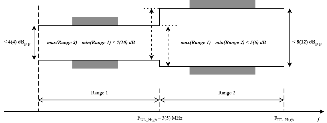
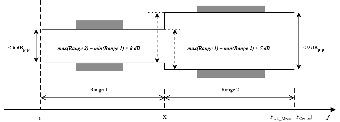
    The function evaluates the peak-to-peak ripple of the equalizer coefficients independently across Range 1 and Range 2 frequency regions defined by carrier and channel. It derives EVM equalizer coefficients using least squares (LS) estimation from the equalized symbols grid eqGrid and reference symbols grid refGrid. Then, the function scales these derived coefficients by zero-forcing (ZF) equalizer weights, computed from the channel estimate Hest to account for channel-dependent layer gain.

    The function returns the ripple values and pass or fail status in metrics. It returns the equalizer coefficients and range indices in info. To use this syntax you must have equalized symbols, reference symbols, and a channel estimate.

    example

    [metrics,info] = nrSpectralFlatness(carrier,channel,rxGrid) measures EVM equalizer spectral flatness for uplink allocations from the received grid rxGrid. The function performs channel estimation, using demodulation reference signal (DM-RS) symbols from rxGrid, and constructs equalized symbols using ZF equalization. It reconstructs the transmitted data symbols from the equalized data symbols. The function uses the reconstructed symbols as reference symbols. Then, it derives EVM equalizer coefficients using LS estimation from the equalized and reference symbols.

    example

    [metrics,info] = nrSpectralFlatness(___,Name=Value) specifies options using one or more name-value arguments in addition to any combination of input arguments from the previous syntaxes.

    example

    Examples

    collapse all

    Calculate spectral flatness metrics from an equalized grid, reference grid, and channel estimate. You generate a 5G NR physical uplink shared channel (PUSCH) waveform and add noise to the waveform, performs OFDM demodulation and estimate the channel using demodulation reference signal (DM-RS) symbols. To equalize the received grid and reconstruct reference symbols, you use hard decisions.

    To ensure simulation results are repeatable, initialize the random number generator with a fixed seed. For greater statistical accuracy, run the simulation for multiple time with different seeds and compute the average results.

    rng(1);

    Specify the subcarrier spacing using an nrSCSCarrierConfig object with a resource grid size of 200 resource blocks.

    carrierObj = nrSCSCarrierConfig;
    carrierObj.NSizeGrid = 200;

    Specify the bandwidth part configuration with a 20-RB offset from the carrier grid start and a size of 30 resource blocks.

    bwpObj = nrWavegenBWPConfig;
    bwpObj.SubcarrierSpacing = 15;
    bwpObj.NStartBWP = carrierObj.NStartGrid+20;
    bwpObj.NSizeBWP = 30;

    Create a PUSCH configuration for 5G uplink waveform generation that allocates all 30 PRBs in the bandwidth part.

    puschObj = nrWavegenPUSCHConfig;
    puschObj.PRBSet = 0:29;
    puschObj.NumLayers = 2;

    Configure an uplink carrier for FR1 with a 40 MHz channel bandwidth. Specify 20 subframes to generate a multi-slot waveform for evaluation across multiple measurement intervals.

    ChannelBW = 40;
    NSFrames = 20;
    cfgUL = nrULCarrierConfig( ...
        FrequencyRange="FR1", ...
        ChannelBandwidth=ChannelBW, ...
        NumSubframes=NSFrames, ...
        SCSCarriers={carrierObj}, ...
        BandwidthParts={bwpObj}, ...
        PUSCH={puschObj});

    Generate the uplink waveform using the nrWaveformGenerator function.

    [waveform,waveInfo] = nrWaveformGenerator(cfgUL);

    Add additive white Gaussian noise (AWGN) to the transmitted waveform to simulate channel noise.

    SNRdB = 40;
    SNR = 10^(SNRdB/10);
    R = size(waveform,2);
    N0 = 1/sqrt(2*R*double(waveInfo.ResourceGrids.Info.Nfft)*SNR);
    noise = N0*complex(randn(size(waveform)),randn(size(waveform)));
    waveform = waveform + noise;

    Create a configuration for a PUSCH for receiver processing using parameters from the PUSCH configuration for waveform generation.

    pusch = nrPUSCHConfig;
    pusch.NSizeBWP = bwpObj.NSizeBWP;
    pusch.NStartBWP = bwpObj.NStartBWP;
    pusch.Modulation = puschObj.Modulation;
    pusch.NumLayers = puschObj.NumLayers;
    pusch.MappingType = puschObj.MappingType;
    pusch.SymbolAllocation = puschObj.SymbolAllocation;
    pusch.PRBSet = puschObj.PRBSet;
    pusch.NumAntennaPorts = puschObj.NumAntennaPorts;
    pusch.DMRS = puschObj.DMRS;

    Create a carrier configuration for OFDM demodulation and channel estimation using the same carrier and BWP settings used to generate the uplink waveform.

    carrier = nrCarrierConfig;
    carrier.NCellID = cfgUL.NCellID;
    carrier.NSizeGrid = carrierObj.NSizeGrid;
    carrier.NStartGrid = carrierObj.NStartGrid;
    carrier.SubcarrierSpacing = carrierObj.SubcarrierSpacing;
    carrier.CyclicPrefix = bwpObj.CyclicPrefix;
    carrier.NSlot = 0;

    Perform OFDM demodulation on the received waveform using the nrOFDMDemodulate function. Set the cyclic prefix fraction to 0.5 to align FFT timing to the middle of the cyclic prefix.

    samplerate = waveInfo.ResourceGrids.Info.SampleRate;
    carrierFreq = cfgUL.CarrierFrequency;
    
    rxGrid = nrOFDMDemodulate(carrier,waveform, ...
        CyclicPrefixFraction=0.5, ...
        SampleRate=samplerate, ...
        CarrierFrequency=carrierFreq);

    Calculate the number of subcarriers, OFDM symbols per slot, and transmission layers from the carrier and channel configuration.

    K = carrier.NSizeGrid*12;
    L = carrier.SymbolsPerSlot;
    P = pusch.NumLayers;
    numSlots = NSFrames*carrier.SlotsPerSubframe;

    Create the DM-RS reference grid for channel estimation. Extract the DM-RS symbols and DM-RS indices using the nrPUSCHDMRS and nrPUSCHDMRSIndices function respectively.

    refGridDMRS = zeros(K,L*numSlots,P);
    
    for nSlot = 0:numSlots-1
        carrier.NSlot = nSlot;
        dmrsInd = nrPUSCHDMRSIndices(carrier,pusch);
        dmrsSym = nrPUSCHDMRS(carrier,pusch);
        slotGrid = nrResourceGrid(carrier,P);
        slotGrid(dmrsInd) = dmrsSym;
        refGridDMRS(:,nSlot*L+(1:L),:) = slotGrid;
    end

    Perform channel estimation using the received grid and DM-RS reference grid.

    [H,nVar] = nrChannelEstimate(rxGrid,refGridDMRS);

    Perform equalization on the received grid using nrEqualizeMMSE.

    H1 = reshape(H,[K*L*numSlots, R, P]);
    rxFlat = reshape(rxGrid,[K*L*numSlots, R]);
    eqFlat = nrEqualizeMMSE(rxFlat, H1, nVar);
    eqGrid = reshape(eqFlat,[K,L*numSlots, P]);

    Construct the reference grid by performing hard slicing on the equalized symbols. Demodulate and remodulate the equalized PUSCH symbols to obtain reference symbols for each slot.

    refGrid = zeros(K,L*numSlots,P);
    
    for nSlot = 0:numSlots-1
        carrier.NSlot = nSlot;
        slotSymbols = nSlot*L + (1:L);
    
        dataInd = nrPUSCHIndices(carrier,pusch);
        dmrsInd = nrPUSCHDMRSIndices(carrier,pusch);
        dmrsSym = nrPUSCHDMRS(carrier,pusch);
    
        eqSlot = eqGrid(:,slotSymbols,:);
        refSlot = nrResourceGrid(carrier,P);
    
        dataSymbols = eqSlot(dataInd);
        refBits = nrSymbolDemodulate(dataSymbols(:),pusch.Modulation,DecisionType="hard");
        ref = nrSymbolModulate(refBits,pusch.Modulation);
        refSlot(dataInd) = ref;
        refSlot(dmrsInd) = dmrsSym;
        refGrid(:,slotSymbols,:) = refSlot;
    end

    Measure EVM and spectral flatness for each slot. Extract the symbols corresponding to each slot, and then compute the EVM and spectral flatness for that slot using the nrEVM and nrSpectralFlatness function, respectively.

    evmArray = zeros(numSlots,1);
    metricsArray = cell(numSlots,1);
    infoArray = cell(numSlots,1);
    
    for nSlot = 0:numSlots-1
        carrier.NSlot = nSlot;
        slotSymbols = nSlot*L + (1:L);
        EVM = nrEVM(eqGrid(:,slotSymbols,:),refGrid(:,slotSymbols,:));
        evmArray(nSlot+1) = EVM;
        [metrics,info] = nrSpectralFlatness(carrier,pusch, ...
            eqGrid(:,slotSymbols,:), ...
            refGrid(:,slotSymbols,:), ...
            H(:,slotSymbols,:,:), ...
            k0=0,FrequencyRange=cfgUL.FrequencyRange, ...
            CarrierFrequency=cfgUL.CarrierFrequency, ...
            ChannelBandwidth=cfgUL.ChannelBandwidth);
    
        metricsArray{nSlot+1} = metrics;
        infoArray{nSlot+1} = info;
    end

    Display the EVM and spectral flatness results for first slot.

    EVM = evmArray(1)
    EVM = 
    0.4237
    
    metrics = metricsArray{1}
    metrics = struct with fields:
         RP1: [0.2868 0.3616]
         RP2: [0×2 double]
        RP12: [0×2 double]
        RP21: [0×2 double]
        Pass: 1
    
    
    info = infoArray{1}
    info = struct with fields:
        EqualizerCoefficients: [2400×2 double]
                Range1Indices: [360×1 uint32]
                Range2Indices: [0×1 uint32]


    To ensure simulation results are repeatable, initialize the random number generator with a fixed seed. For greater statistical accuracy, run the simulation for multiple time with different seeds and compute the average results.

    rng(1);

    Specify the subcarrier spacing configuration with 30 kHz and a resource grid size of 51 resource blocks.

    carrierObj = nrSCSCarrierConfig;
    carrierObj.NSizeGrid = 51;
    carrierObj.SubcarrierSpacing = 30;

    Specify a bandwidth part configuration that spans the full carrier grid with 30 kHz subcarrier spacing.

    bwpObj = nrWavegenBWPConfig;
    bwpObj.SubcarrierSpacing = 30;
    bwpObj.NStartBWP = carrierObj.NStartGrid;
    bwpObj.NSizeBWP = carrierObj.NSizeGrid;

    Create a PUSCH configuration for 5G uplink waveform generation with 16-QAM modulation that allocates all 51 PRBs on a single spatial layer.

    puschObj = nrWavegenPUSCHConfig;
    puschObj.PRBSet = 0:50;
    puschObj.NumLayers = 1;
    puschObj.Modulation = "16QAM";

    Create an uplink carrier configuration for FR1 with a 20 MHz channel bandwidth. Specify 10 subframes to generate a multi-slot waveform.

    ChannelBW = 20;
    NSFrames = 10;
    cfgUL = nrULCarrierConfig( ...
        FrequencyRange="FR1", ...
        ChannelBandwidth=ChannelBW, ...
        NumSubframes=NSFrames, ...
        SCSCarriers={carrierObj}, ...
        BandwidthParts={bwpObj}, ...
        PUSCH={puschObj});

    Generate the uplink waveform using nrWaveformGenerator.

    [waveform,waveInfo] = nrWaveformGenerator(cfgUL);

    Add AWGN to the transmitted waveform to simulate channel noise.

    SNRdB = 40;
    SNR = 10^(SNRdB/10);
    R = size(waveform,2);
    N0 = 1/sqrt(2.0*R*double(waveInfo.ResourceGrids.Info.Nfft)*SNR);
    noise = N0*complex(randn(size(waveform)),randn(size(waveform)));
    waveform = waveform + noise;

    Create a configuration for a PUSCH for receiver processing using parameters from the PUSCH configuration for waveform generation. The nrSpectralFlatness function uses these PUSCH properties to generate DM-RS symbols for channel estimation and determine the allocated resource elements on which it performs equalization.

    pusch = nrPUSCHConfig;
    pusch.NSizeBWP = bwpObj.NSizeBWP;
    pusch.NStartBWP = bwpObj.NStartBWP;
    pusch.Modulation = puschObj.Modulation;
    pusch.NumLayers = puschObj.NumLayers;
    pusch.MappingType = puschObj.MappingType;
    pusch.SymbolAllocation = puschObj.SymbolAllocation;
    pusch.PRBSet = puschObj.PRBSet;
    pusch.NumAntennaPorts = puschObj.NumAntennaPorts;
    pusch.DMRS = puschObj.DMRS;

    Create a carrier configuration.

    carrier = nrCarrierConfig;
    carrier.NCellID = cfgUL.NCellID;
    carrier.NSizeGrid = carrierObj.NSizeGrid;
    carrier.NStartGrid = carrierObj.NStartGrid;
    carrier.SubcarrierSpacing = carrierObj.SubcarrierSpacing;
    carrier.CyclicPrefix = bwpObj.CyclicPrefix;
    carrier.NSlot = 0;

    Perform OFDM demodulation with FFT timing aligned to the middle of the cyclic prefix.

    rxGrid = nrOFDMDemodulate(carrier,waveform, ...
        CyclicPrefixFraction=0.5, ...
        SampleRate=waveInfo.ResourceGrids.Info.SampleRate, ...
        CarrierFrequency=cfgUL.CarrierFrequency);

    Calculate the total number of slots in the received grid.

    numSlots = NSFrames*carrier.SlotsPerSubframe;

    Measure spectral flatness for each slot using the nrSpectralFlatness function.

    metricsArray = cell(numSlots,1);
    infoArray = cell(numSlots,1);
    
    for nSlot = 0:numSlots-1
        carrier.NSlot = nSlot;
        slotSymbols = nSlot*carrier.SymbolsPerSlot + (1:carrier.SymbolsPerSlot);
        [metrics,info] = nrSpectralFlatness(carrier,pusch, ...
            rxGrid(:,slotSymbols,:), ...
            FrequencyRange=cfgUL.FrequencyRange, ...
            ChannelBandwidth=cfgUL.ChannelBandwidth);
        metricsArray{nSlot+1} = metrics;
        infoArray{nSlot+1} = info;
    end

    Display the spectral flatness results for the first slot.

    metrics = metricsArray{1}
    metrics = struct with fields:
         RP1: 0.1047
         RP2: 0.1031
        RP12: 0.0969
        RP21: 0.1109
        Pass: 1
    
    
    info = infoArray{1}
    info = struct with fields:
        EqualizerCoefficients: [612×1 double]
                Range1Indices: [467×1 uint32]
                Range2Indices: [145×1 uint32]


    Measure EVM equalizer spectral flatness for a pi/2-BPSK PUSCH waveform. Derive the impulse response from the equalizer coefficients according to TS 38.521-1 Annex E.4.4.2. Then, verify the requirements specified in TS 38.101-1 Section 6.4.2.4.

    Note: The example does not model or apply an additional transmitter spectral shaping filter.

    To ensure simulation results are repeatable, initialize the random number generator with a fixed seed. For greater statistical accuracy, run the simulation for multiple time with different seeds and compute the average results.

    rng(1);

    Specify a subcarrier spacing configuration with 15 kHz and a resource grid size of 200 resource blocks.

    carrier = nrCarrierConfig;
    carrier.NSizeGrid = 200;
    carrier.NStartGrid = 0;
    carrier.SubcarrierSpacing = 15;

    Create a configuration for a PUSCH that uses pi/2-BPSK modulation. Enable transform precoding for DFT-s-OFDM.

    pusch = nrPUSCHConfig;
    pusch.NSizeBWP = 30;
    pusch.NStartBWP = 20;
    pusch.Modulation = "pi/2-BPSK";
    pusch.PRBSet = 0:pusch.NSizeBWP-1;
    pusch.TransformPrecoding = true;

    Calculate the PUSCH data indices.

    [puschIndices,puschInfo] = nrPUSCHIndices(carrier,pusch);

    Define a random codeword using the bit capacity of the PUSCH configuration.

    cw = randi([0 1],puschInfo.G,1);

    Calculate, data symbols, DM-RS indices, and DM-RS symbols for your PUSCH configuration.

    puschSym = nrPUSCH(carrier,pusch,cw);
    puschDMRSInd = nrPUSCHDMRSIndices(carrier,pusch);
    puschDMRSSym = nrPUSCHDMRS(carrier,pusch);

    Construct the transmitted grid.

    txGrid = nrResourceGrid(carrier);
    txGrid(puschIndices) = puschSym;
    txGrid(puschDMRSInd) = puschDMRSSym;

    OFDM modulate the grid to generate the time-domain waveform.

    [txWaveform,winfo] = nrOFDMModulate(carrier,txGrid);

    Add noise to the transmit waveform.

    evmPercent = 2.0;
    noise = evmPercent/(100*sqrt(winfo.Nfft))*randn(size(txWaveform),like=1i);
    rxWaveform = txWaveform + noise;

    Perform OFDM demodulation with FFT timing aligned to the middle of the cyclic prefix.

    rxGrid = nrOFDMDemodulate(carrier,rxWaveform);

    Use the DM-RS symbols to create a reference grid to use for channel estimation.

    refGrid = zeros(size(rxGrid));
    refGrid(puschDMRSInd) = puschDMRSSym;

    Calculate the channel estimate using the received grid and reference grid.

    [H,nVar] = nrChannelEstimate(rxGrid,refGrid,CyclicPrefix = carrier.CyclicPrefix,CDMLengths = pusch.DMRS.CDMLengths);
    [rxGrid,refGrid,H] = nrExtractResources(1:numel(rxGrid),rxGrid,refGrid,H);

    Perform channel equalization on the extracted PUSCH resource grids.

    eqGrid = nrEqualizeMMSE(rxGrid,H,nVar);

    Perform hard-decision on the equalized PUSCH symbols to generate the reference symbols.

    refBits = nrSymbolDemodulate(eqGrid(puschIndices),pusch.Modulation,DecisionType="hard");
    ref = nrSymbolModulate(refBits,pusch.Modulation);

    Create the reference grid by placing the reference data symbols on the allocated PUSCH resource elements.

    refGrid(puschIndices) = ref;

    Calculate the spectral flatness metric using the nrSpectralFlatness function, additionally returning the equalizer coefficients.

    [metrics,info] = nrSpectralFlatness(carrier,pusch,eqGrid,refGrid,H);

    For pi/2-BPSK, the equalizer coefficients capture the combined frequency response of the transmitter, including the spectral shaping filter. Following TS 38.521-1 Annex E.4.4.2, derive the spectral shaping filter impulse response from the equalizer coefficients. Extract the equalizer coefficients over the allocated bandwidth part and compute the inverse frequency response. Apply an inverse FFT to obtain the corresponding impulse response.

    M = pusch.NSizeBWP*12; 
    bwpSCs = (pusch.NStartBWP)*12 + (1:M);
    EC_f = info.EqualizerCoefficients;
    EC_alloc = EC_f(bwpSCs,:);
    H_inv = 1./EC_alloc;
    a_tau = ifft(H_inv,M);

    Normalize the impulse response with respect to its zero-delay tap.

    a_tilde = a_tau/a_tau(1);

    Verify that the normalized impulse response satisfies the spectral shaping filter requirements defined in TS 38.101-1 Section 6.4.2.4. The peak magnitude must occur at the zero-delay tap. The magnitude of each remaining tap must be at least 15 dB below the peak.

    peakAtZero = all(abs(a_tilde(1)) >= abs(a_tilde(2:end)))
    peakAtZero = logical
       1
    
    
    a_tilde_dB = 20*log10(abs(a_tilde));
    sidelobeLevels = a_tilde_dB(2:end-1); 
    below15dB = all(sidelobeLevels < -15)
    below15dB = logical
       1


    Input Arguments

    collapse all

    Carrier configuration parameters for a specific OFDM numerology, specified as an nrCarrierConfig object. This function uses only these properties of the object:

    Physical uplink shared channel configuration, specified as an nrPUSCHConfig object. This function uses only these properties of the object:

    Received OFDM symbols grid, specified as a K-by-L-by-R complex-valued array.

    • K is the number of subcarriers, equal to carrier.NSizeGrid*12.

    • L is the number of OFDM symbols per slot.

    • R is the number of receive antennas.

    Data Types: double | single
    Complex Number Support: Yes

    Estimated channel information, specified as a K-by-L-by-R-by-P complex-valued array or NRE-by-R-by-P complex-valued array.

    • K is the number of subcarriers, equal to carrier.NSizeGrid*12.

    • L is the number of OFDM symbols per slot.

    • NRE is the number of resource elements, equal to K × L.

    • R is the number of receive antennas.

    • P is the number of transmitted layers.

    Data Types: double | single
    Complex Number Support: Yes

    Reference symbols grid, specified as a K-by-L-by-P complex-valued array or an NRE-by-P complex-valued matrix. The grid must not exceed one slot duration.

    • K is the number of subcarriers, equal to carrier.NSizeGrid*12.

    • L is the number of OFDM symbols per slot.

    • NRE is the number of resource elements, equal to K × L.

    • P is the number of transmitted layers.

    Note

    The dimensions of the eqGrid and refGrid arguments must be the same.

    Data Types: double | single
    Complex Number Support: Yes

    Equalized OFDM symbols grid, specified as a K-by-L-by-P complex-valued array or an NRE-by-P complex-valued matrix.

    • K is the number of subcarriers, equal to carrier.NSizeGrid*12.

    • L is the number of OFDM symbols per slot.

    • NRE is the number of resource elements, equal to K × L.

    • P is the number of transmitted layers.

    Note

    The dimensions of the eqGrid and refGrid arguments must be the same.

    Data Types: double | single
    Complex Number Support: Yes

    Name-Value Arguments

    collapse all

    Specify optional pairs of arguments as Name1=Value1,...,NameN=ValueN, where Name is the argument name and Value is the corresponding value. Name-value arguments must appear after other arguments, but the order of the pairs does not matter.

    Example: nrSpectralFlatness(carrier,channel,rxGrid,FrequencyRange="FR1",ChannelBandwidth=10) specifies to use NR frequency range 1 and a channel bandwidth of 10 MHz.

    NR frequency range, specified as one of these values.

    • "FR1" — Frequency range 1 (FR1) that corresponds to frequencies from 410 MHz to 7.125 GHz.

    • "FR2" — Frequency range 2 (FR2) that corresponds to frequencies from 24.25 GHz to 52.6 GHz (FR2-1) and from 52.6 GHz to 71 GHz (FR2-2).

    Data Types: char | string

    Frequency offset index in subcarriers relative to Point A, specified as a nonnegative integer. Point A defines the common reference point for resource block grids. The function defines carrier positions relative to Point A. The function uses this offset to determine absolute frequency positions for Range 1 and Range 2 boundaries.

    Example: k0=10, specifies a frequency offset of 10 subcarriers from Point A.

    Data Types: double | single

    Channel bandwidth in MHz, specified as a positive scalar. Standard channel bandwidths defined in TS 38.101-1 and TS 38.101-2 are:

    • FR1 — 3, 5, 10, 15, 20, 25, 30, 35, 40, 45, 50, 60, 70, 80, 90, or 100

    • FR2 — 50, 100, 200, 400, 800, 1600, or 2000

    The function accepts any positive channel bandwidth value.

    When you set this argument to [], the function derives the channel bandwidth from carrier.NSizeGrid and carrier.SubcarrierSpacing.

    Data Types: double | single

    Frequencies of lower and upper edge of operating band in MHz, specified as a two-element vector of the form [FUL_Low FUL_High], as defined in Table 5.5-1 of TS 38.101-1.

    When you specify band edges, the function calculates the ChannelBandwidth as FUL_High – FUL_Low and ignores the ChannelBandwidth argument. If you specify this argument, you must also specify the CarrierFrequency argument.

    Dependencies

    To use this name-value argument, you must specify the FrequencyRange argument as "FR1".

    Data Types: double | single

    Carrier frequency, specified as a nonnegative scalar. For FR1, when you specify BandEdges, the CarrierFrequency value determines the location of the carrier within the operating band. When you specify BandEdges, you must also specify CarrierFrequency as a frequency within the bounds specified by BandEdges. Units are in Hz.

    Data Types: double | single

    DC subcarrier location for the carrier, specified as one of these values:

    • [] — The function includes all subcarriers in the measurement.

    • Nonnegative integer — The function excludes the subcarrier at the specified location from the spectral flatness measurement.

    You can use this argument when the transmitter has a DC offset that affects the measurement.

    Example: TxDirectCurrentLocation=312 excludes subcarrier 312 from the measurement.

    Dependencies

    To use this name-value argument, you must specify the rxGrid argument.

    Data Types: double | single

    Tolerance limit for the ripple measurements in dB, specified as a nonnegative scalar. This value defines how much the measured ripple can exceed the limit defined by TS 38.101-1 and 38.101-2 before the function reports a failure. The function reports a failure only when the measured ripple exceeds the defined limit by more than this value. Units are in dB.

    Example: TestTolerance=0.5 adds 0.5 dB margin to all ripple limits.

    Data Types: double | single

    Flag for extreme measurement conditions, specified as a numeric or logical 1 (true) or 0 (false).

    • false — Normal measurement conditions. The function applies the standard ripple limits for normal conditions as defined in TS 38.521-1 and TS 38.521-2.

    • true — Extreme measurement conditions. The function applies the relaxed ripple limits for extreme conditions as defined in TS 38.521-1 and TS 38.521-2.

    Data Types: logical

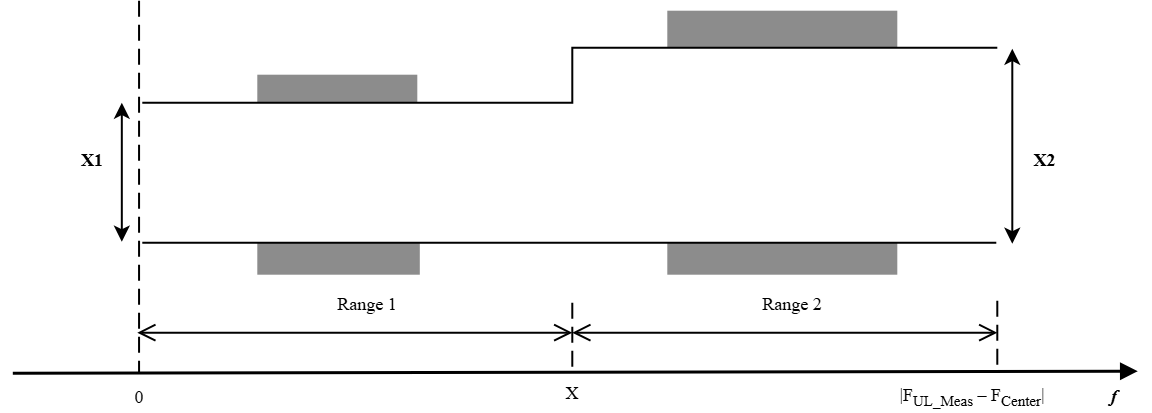
    Frequency regions that belong to Range 1 and Range 2, specified as a positive scalar. This argument partitions the carrier bandwidth into Range 1 and Range 2. Units are in MHz.

    • For FR1 — Range 1 consists of subcarriers that are at least X MHz away from both band edges. Range 2 consists of subcarriers within X MHz of either band edge.

    • For FR2 — Range 1 consists of subcarriers within X MHz of the channel center. Range 2 consists of subcarriers outside this region.

    • For pi/2‑BPSK modulation — Range 1 consists of subcarriers within X MHz of the bandwidth part (BWP) center. Range 2 consists of subcarriers outside this region.

    When you set this argument to [], the function determines X from the specified frequency range and modulation scheme:

    • FR1 — The function sets X to 3 MHz. When IsExtremeCondition is true, the function sets X to 5 MHz.

    • FR2 — The function sets X to 30% of the ChannelBandwidth value, measured from the channel center.

    • pi/2-BPSK — The function sets X to 25% of the BWP bandwidth, measured from the BWP center.

    Example: nrSpectralFlatness(carrier,channel,rxGrid,FrequencyRange="FR1",X=5) specifies that subcarriers within 5 MHz of either band edge belong to Range 2, and the remaining subcarriers belong to Range 1.

    Data Types: double | single

    Output Arguments

    collapse all

    Spectral flatness metrics, returned as a structure containing these fields:

    FieldValueDescription
    RP1Numeric vector of size 1-by-PMaximum peak-to-peak ripple of equalizer coefficients in Range 1, in dB.
    RP2Numeric vector of size 1-by-PMaximum peak-to-peak ripple of equalizer coefficients in Range 2, in dB.
    RP12Numeric vector of size 1-by-PRelative difference between the maximum equalizer coefficient in Range 1 and the minimum equalizer coefficient in Range 2, in dB.
    RP21Numeric vector of size 1-by-PRelative difference between the maximum equalizer coefficient in Range 2 and the minimum equalizer coefficient in Range 1, in dB.
    PassLogical scalarLogical output that indicates whether the spectral flatness requirements are satisfied across all layers.

    The function returns Pass as true when all ripple values satisfy specification limits, including TestTolerance.

    Data Types: Struct

    Spectral flatness processing information, returned as a structure containing these fields:

    FieldValueDescription
    EqualizerCoefficientsComplex-valued matrix of size K-by-PEqualizer coefficients per subcarrier per layer. For pi/2-BPSK modulation, use these coefficients to evaluate the shaping filter response.
    Range1IndicesColumn vectorIndices of subcarriers that fall into Range 1.
    Range2IndicesColumn vectorIndices of subcarriers that fall into Range 2.

    Data Types: struct

    More About

    collapse all

    References

    [1] 3GPP TS 38.101-1. “NR; User Equipment (UE) radio transmission and reception; Part 1: Range 1 Standalone.” 3rd Generation Partnership Project; Technical Specification Group Radio Access Network.

    [2] 3GPP TS 38.101-2. “NR; User Equipment (UE) radio transmission and reception; Part 2: Range 2 Standalone.” 3rd Generation Partnership Project; Technical Specification Group Radio Access Network.

    [3] 3GPP TS 38.521-1. “NR; User Equipment (UE) radio transmission and reception; Part 1: Range 1 Standalone.” 3rd Generation Partnership Project; Technical Specification Group Radio Access Network.

    [4] 3GPP TS 38.521-2. “NR; User Equipment (UE) radio transmission and reception; Part 2: Range 2 Standalone.” 3rd Generation Partnership Project; Technical Specification Group Radio Access Network.

    Extended Capabilities

    expand all

    C/C++ Code Generation
    Generate C and C++ code using MATLAB® Coder™.

    GPU Code Generation
    Generate CUDA® code for NVIDIA® GPUs using GPU Coder™.

    Version History

    Introduced in R2026b