Display Measurements with Cockpit Instruments
You can view signal data using any of the flight instrument blocks. This example uses the HL-20 with Flight Instrumentation Blocks model. In this example, connect a gauge so that you can view the aircraft heading.
To open the model, at the MATLAB® command window, enter
openExample('HL20Gauges').Open the Visualization subsystem.
There is an existing Airspeed Indicator block in the model.
Add a second Airspeed Indicator block from the Flight Instruments library to the subsystem.
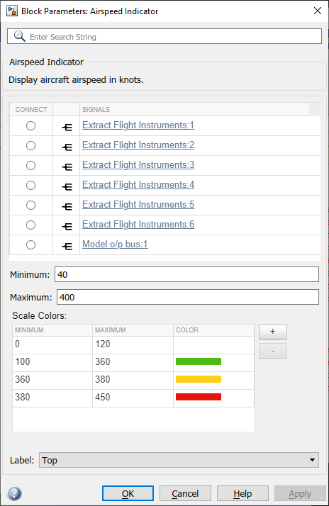
Open the new Airspeed Indicator block.
Select the Extract Flight Instruments block.
In the new Airspeed Indicator block, observe that the block connection table is filled with signals from the Extract Flight Instruments block that you can observe.

Select the option button next to
Extract_Gauges:2in the connection table.To connect the
Extract_Gauges:2signal to the Airspeed Indicator block, click OK.Tip
To directly select the signal to connect, on the Extract Flight Instruments block, select the third output port (Roll Flightpath).
Simulate the model and observe the gauge as it registers the data.
To change the signal to connect to, you can:
Select the same or another block and then select another signal in the updated block connection table.
Select another output port for the same or a different block.
Close the model without saving it.
To create a Simulink® model with prewired connections to flight instrument blocks, at the
command line, type
open_system(Simulink.createFromTemplate('asbFlightInstrumentsTemplate.sltx')).
See Also
Airspeed Indicator | Altimeter | Artificial Horizon | Climb Rate Indicator | Exhaust Gas Temperature (EGT) Indicator | Heading Indicator | Revolutions Per Minute (RPM) Indicator | Turn Coordinator