Getting Started with the Spacecraft Dynamics Block
This example shows how to model six degree-of-freedom rigid-body dynamics of a spacecraft or constellation of spacecraft with the Spacecraft Dynamics block from Aerospace Blockset™.
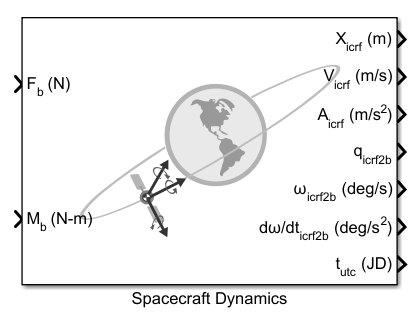
The Spacecraft Dynamics block models translational and rotational dynamics of spacecraft using numerical integration. It computes the position, velocity, attitude, and angular velocity of one or more spacecraft over time. For the most accurate results, use a variable step solver with low tolerance settings (less than 1e-8). Depending on your mission requirements, you can increase speed by using larger tolerances. Doing so may impact the accuracy of the solution.
Define orbital states as a set of orbital elements or as position and velocity state vectors. To propagate orbital states, the block uses the gravity model selected for the current central body. The block also includes external accelerations and forces provided as inputs to the block.
Attitude states are defined using quaternions, direction cosine matrices (DCMs), or Euler angles. To propagate attitude states, the block uses moments provided as inputs to the block and mass properties defined on the block.
This document walks through the various options and configurations available on the block, explains how to model a constellation of spacecraft, and presents an example Simulink® model that implements the Spacecraft Dynamics block for a low-Earth observation satellite. Finally, the equations used by the block are presented.
Block Description
The Spacecraft Dynamics block can be found in the Simulink Library Browser (Aerospace BlocksetSpacecraftSpacecraft Dynamics), or by typing "Spacecraft Dynamics" into the quick insert dialog on the Simulink model canvas. This section provides an overview of the options available on the block, viewed from the Simulink Property Inspector (on the Modeling tab, under Design).
Main Tab
The Main tab includes block-level configuration parameters. All parameters on this tab apply to every spacecraft defined in the block.
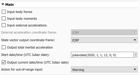
You can specify whether to include:
Body forces defined in the body frame
Body moments defined in the Body frame ports
External accelerations, to include perturbing accelerations in orbit propagation that are not included in the block's internal calculations. By default, the block calculates and uses central body gravity for orbit propagation (see Central Body tab below). Some examples of additional perturbing accelerations that you can include in propagation are those due to atmospheric drag, third body gravity, and solar radiation pressure. You can provide perturbing accelerations in the inertial (ICRF) or fixed-frame coordinate systems, depending on the value set for External acceleration coordinate frame. For more information about fixed-frame coordinate systems used for each central body, see the Coordinate Systems section of the block reference page.
State vector output coordinate frame controls whether position and velocity state outputs from the block are in the inertial (ICRF) or fixed-frame coordinate systems.
You can also specify whether to output total inertial acceleration from the block, which is always in the inertial frame. This value is the total acceleration, including internally computed central body gravity as well as contributions from body forces and external accelerations provided to the block as inputs. Note, the acceleration output port is intended for diagnostic use only. It is not a valid workflow to feed this signal back into the block as an input.
Start date/time is the initial date/time corresponding with the Simulink model start time . It is the assumed epoch for all initial conditions provided on the block. Optionally, you can select Output current date/time to output a time signal from the block to use elsewhere in the simulation.
Mass Tab
Three mass types are available to model mass properties of the spacecraft: Fixed, Simple variable, and Custom Variable.

When Mass type is Fixed, the mass and inertia tensor are held constant at the values provided for Mass and Inertia tensor throughout the simulation. Mass flow rate and rate of change of inertia equal zero.
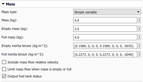
When Mass type is Simple variable, a simplistic approach is taken to vary the mass properties of the spacecraft during the simulation.
An initial Mass, Empty mass (dry), and Full mass (wet) are defined. Mass flow rate is provided to the block via an input port (dm/dt). This value is integrated to calculate the current mass at each time step of the simulation.
Similarly, in this configuration you provide inertia tensor values for the empty and full spacecraft configurations. The current tensor is approximated by linear interpolation between Empty inertia tensor and Full inertia tensor based on the current mass value.
You can optionally add another input port () to the block to provide a mass flow relative velocity using parameter Include mass flow relative velocity. This relative velocity is provided in the Body frame. It is used to calculate the force contribution due to mass being ablated from or added to the spacecraft.
To limit the mass flow rate provided to the block when the current mass is below the empty mass or above the full mass value, use parameter Limit mass flow when mass is empty or full.
Finally, the current fuel status can be output from the block (Fuel Status) based on the current mass. If the current mass exceeds Full mass, the reported status is 1. If the current mass is below Empty mass, the status is -1. When the mass is within the provided operating range, the status is 0.

When Mass type is Custom variable, more flexibility is provided regarding how the mass properties of the spacecraft change over time. However this requires that more values be calculated externally from the block.
In this configuration, block input ports are added for the current mass (m), current inertia tensor (I), and the current rate of change of the inertia tensor (dI/dt).
To provide mass flow relative velocity, you can optionally add another input port () to the block with the Include mass flow relative velocity parameter. This relative velocity is provided in the Body frame. It is used to calculate the force contribution due to mass being ablated from or added to the spacecraft. Therefore, enabling this parameter adds an additional port to the block to provide mass flow rate (dm/dt).
Orbit Tab
The Orbit tab defines initial conditions for the spacecraft as sets of orbital elements or as position and velocity state vectors depending on the value of Initial state format (Orbital elements, ICRF state vector, or Fixed-frame state vector).


For state vector options, provide the initial position and velocity that correspond with Start date/time in the specified coordinate frame.
The Initial state format option Orbital elements is further decomposed by parameter Orbit type.
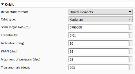
When Orbit type is Keplerian, you specify the traditional set of six Keplerian orbital elements:
Semi-major axis ()
Eccentricity ()
Inclination ()
Right ascension of the ascending node - RAAN ()
Argument of periapsis ()
True anomaly ().
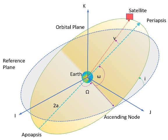
When specifying orbital elements, three orbit types result in undefined elements:
When an orbit is equatorial (inclination equal to zero), RAAN is undefined.
When an orbit is circular (eccentricity equal to zero), argument of periapsis and true anomaly are undefined.
When an orbit is circular and equatorial, all three elements are undefined.
To assist in modeling these conditions, the block provides three additional options for Orbit type in addition to Keplerian.

For non-circular (elliptical) equatorial orbits, inclination always equals zero, and RAAN and Argument of periapsis are replaced with Longitude of periapsis. Longitude of periapsis is the angle between the ICRF X-axis (I) and periapsis. It is equal to the sum of RAAN () and the argument of periapsis ().
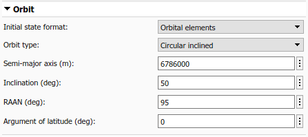
For circular inclined (non-equatorial) orbits, eccentricity always equals zero, and Argument of periapsis and True anomaly are replaced by Argument of latitude. Argument of latitude is the angle between the ascending node and the satellite position vector. It is equal to the sum of the true anomaly () and the argument of periapsis ().

Finally, for circular equatorial orbits, inclination and eccentricity always equal zero, and RAAN, Argument of periapsis, and True anomaly are replaced by True longitude. True longitude is the angle between the ICRF X-axis (I) and the spacecraft position vector. It is equal to sum of true anomaly (), argument of periapsis (), and RAAN ().
Attitude Tab
The Attitude tab defines initial conditions for the attitude of the spacecraft being modeled. Using parameter Attitude reference coordinate frame, you can define attitude with respect to the inertial (ICRF) frame, Fixed-frame, North-East-Down (NED) frame, or local-vertical local-horizontal (LVLH) frame. Initial attitude and body angular rate parameters provided to the block are assumed to be defined with respect to the specified frame. The attitude and body angular rate outputs from the block also use this frame.
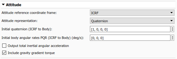
To specify what representation method to use for attitude, use the Attitude representation parameter. Depending on the value selected, the Initial attitude parameter displays as Initial quaternion, Initial DCM, or Initial Euler angles. It expects the dimensions of the provided initial condition to match that representation. Additionally, the attitude output port from the block uses the specified representation.
The initial attitude rate of change, Initial body angular rates PQR, and the corresponding output port () are always defined as angular rates, regardless of the selection made for Attitude representation.
You can also specify whether to Output total inertial angular acceleration () from the block. This output is always defined with respect to the inertial (ICRF) frame. If Include gravity gradient torque is selected, this value is the total angular acceleration due to moments provided as inputs to the block, and gravity gradient torque computed internally. Note, the angular acceleration output port is intended for diagnostic use only. It is not a valid workflow to feed this signal back into the block as an input.
If enabled, gravity gradient torque calculations treat the central body as a spherical body. The overall contribution due to gravity gradient torque is small. Treating the central body as a spherical body is generally sufficient for most applications. If a higher level of accuracy is required, gravity gradient torque values can be calculated externally and provided to the block as a moment. See the block equations section below for the equations implemented by the block.
Central Body Tab
Use the Central Body tab to provide information about the physical properties, gravitational potential model, and orientation of the celestial body around which the spacecraft is in orbit. All planets in our solar system are available, as well as the Earth Moon (Luna). Custom central bodies may also be defined. First, look at the various options for parameter Gravitational potential model (None, Point-mass, Oblate ellipsoid (J2), and Spherical harmonics).

None is available for all central bodies. This option does not include any internally calculated gravitational acceleration in the system equations. Use this option in conjunction with the external acceleration input port if you have your own gravity model that you would like to use. When using option None with a custom central body, only planetary Rotational rate is required.
Point-mass is available for all central bodies. This option treats the central body as a point mass, and computes gravitational acceleration using Newtons law of universal gravitation. When using option Point-mass with a custom central body, you must provide Equatorial radius, Flattening, Gravitational parameter (), and planetary Rotational rate.
Oblate ellipsoid (J2) is available for all central bodies. This option includes the perturbing effects of the second-degree, zonal harmonic gravity coefficient, , accounting for the oblateness of the central body. When using option Oblate ellipsoid (J2) with a custom central body, you must provide Equatorial radius, Flattening, Gravitational parameter (), Second degree zonal harmonic (J2), and planetary Rotational rate.
Spherical harmonics is available only when central body is set to Earth, Moon, Mars, or Custom. The Spherical harmonic model options available for each central body are listed in this table:

You must also specify a value for Degree that is below the maximum degree supported by the selected spherical harmonic model. Recommended and maximum degree values for each model are provided below:

When using option Spherical harmonics with a custom central body, you must provide planetary Rotational rate, a Spherical harmonic coefficient file (.mat), and Degree. For more information about this file, see the parameter description in the Spacecraft Dynamics block reference page.
All planetary constants used by the block are from NASA JPL Planetary and Lunar Ephemerides DE405.
All J2 constant values are from NASA Space Science Data Coordinated Archive (NSSDCA).
If you need alternate constant values, use the Custom option for Central body.
In addition to gravity, the Central Body tab includes information about the orientation of the central body. Available parameters depend on the currently selection Central body. All central bodies except Earth, Moon, and Custom use planetary rotational pole and meridian definitions from the Report of the IAU/IAG Working Group on cartographic coordinates and rotational elements: 2006. Options specific to Earth, Moon, and Custom are discussed below.
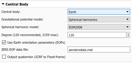
When Central body is Earth, the fixed-frame coordinate system used by the block is the ITRF. By default, the transformation between ICRF and ITRF uses Earth orientation parameter (EOP) data provided to parameter IERS EOP data file. To generate an up-to-date EOP data file, use the Aerospace Toolbox function aeroReadIERSData(). This function calls out to the IERS data server and saves up-to-date EOP data to a MAT-file. To exclude Earth orientation parameter data from the transformation, clear Use Earth orientation parameters (EOPs).
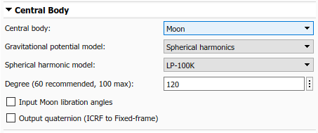
When Central body is Moon, you can provide Moon libration angles as inputs to the block by selecting Input Moon libration angles. When this option is selected, an input port is added to the block. In this case, libration angles are supplied at each time step of the simulation to use in the transformation between the fixed frame and ICRF. You can compute libration angles using the Moon Libration block. When using libration angles, the fixed-frame coordinate system for Moon is the Mean Earth/pole axis frame (ME). This frame is realized by two transformations. First, the block transforms values in the ICRF frame to the Principal Axis system (PA), which is the axis defined by the libration angles provided as inputs to the block. The block then transforms states into the ME system using a fixed rotation from the Report of the IAU/IAG Working Group on cartographic coordinates and rotational elements: 2006. If the Input Moon libration angles check box is cleared, the fixed frame is defined by the directions of the poles of rotation and prime meridians defined in the Report of the IAU/IAG Working Group on cartographic coordinates and rotational elements: 2006.
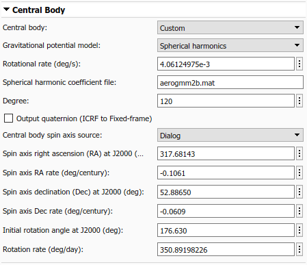
When Central body is Custom, there are two options to provide rotation pole and meridian data to the block, depending on the value of parameter Central body spin axis source. To provide current right ascension, declination, and rotational rate values as inputs to the block at each timestep, set the source to Port. To provide initial conditions for right ascension, declination, and rotation angle at J2000 (JD 2451545.0, i.e. 2000 January 1 12 hours TDB) as well as corresponding rate of change for each value, set the source to Dialog. These parameters align with the terminology and equations presented in the Report of the IAU/IAG Working Group on cartographic coordinates and rotational elements: 2006.
Finally, for all central bodies, you can optionally output a quaternion that performs a position transformation from ICRF to the fixed-frame by selecting Output quaternion (ICRF to Fixed-frame).
Units Tab
The Units tab defines the unit system, the Angle units (Degrees or Radians), and the time format used by the block.

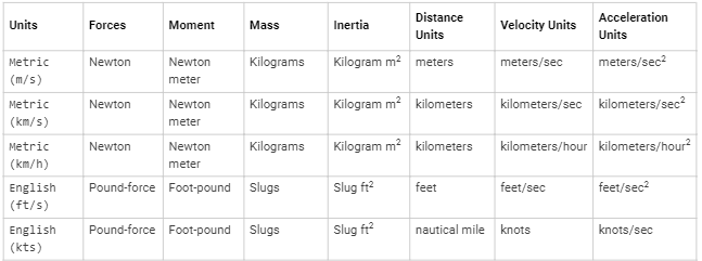
When Time format is Julian date, Start date/time and the block optional time output port use a scalar Julian date value. When set to Gregorian, both values are a 1x6 array of the form [Year, Month, Day, Hour, Minute, Second]. The corresponding units for each option of parameter Units are presented in the table below. Expected units in each parameter and port label on the block are updated automatically when Units is changed.
Modeling a Satellite Constellation
Up to this point we have modeled a single spacecraft with the Spacecraft Dynamics block. However, the block can also be configured to model a constellation of satellites/spacecraft. The number of spacecraft being modeled is determined by the size of the initial conditions provided. If more than one value is provided for a parameter in the Mass, Orbit, or Attitude tabs, the block outputs a constellation of satellites. Any parameter that has a single value provided is expanded and applied to all satellites in the constellation. For example, if a single value is provided for all parameters on the block except True anomaly which contains 6 values, a constellation of 6 satellites is created, varying true anomaly only.
![Spacecraft Dynamics block icon showing expansion for six satellites. Property inspector displays parameter settings. True anomaly set to [0 60 120 180 240 300]](../examples/aeroblks/win64/GettingStartedWithTheSpacecraftDynamicsBlockExample_22.png)
This behavior applies to all spacecraft initial conditions (all dialog boxes in the Mass, Orbit, or Attitude tabs). Above, initial condition parameter in the Mass, Orbit, or Attitude tabs must contain a single value expanded to all satellite or 6 individual values, one for each satellite.
![Spacecraft Dynamics block icon showing expansion for six satellites. Property inspector displays parameter settings. Inclination marks invalid inclination value of [50 75 90]](../examples/aeroblks/win64/GettingStartedWithTheSpacecraftDynamicsBlockExample_23.png)
The same expansion behavior also applies to block input ports. All input ports support expansion expect Moon libration angles (when Central body is Moon) and spin-axis Right ascension, declination, and rotation angle (when Central body is Custom). Moon libration angles and spin-axis orientation inputs are time-dependent values, and therefore always apply to all spacecraft being modeled. All other ports accept a single value expanded to all spacecraft being modeled, or individual values applied to each spacecraft (6, in the above example).
Modeling a Lunar Orbit
To demonstrate this port expansion behavior, consider a new scenario in which we have twin lunar orbiters separated along their orbit track by 200km. Each satellite operates independently of the other, so different forces and moments are applied to each. However, we want to include the gravitational impact of Earth as a perturbing acceleration on both satellites. We assume that the difference in gravitational acceleration due to Earth in a lunar orbit across 200km is negligible. Our resulting block is shown below.
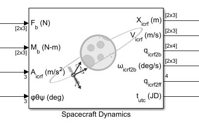
There are separate force and moment input values for each satellite, however a single external acceleration input is expanded and applied to both spacecraft. As stated above, Moon libration angles are always spacecraft-independent.
The state outputs from the blocks always match the total number of spacecraft being modeled, where rows correspond with individual spacecraft. There are also two time-dependent outputs from the block, the current time and the transformation from inertial frame to fixed frame .
Simulink Model Example
Now, explore an example model that uses the Spacecraft Dynamics block to simulate an Earth observation satellite.
mdl = "SpacecraftDynamicsBlockExampleModel";
open_system(mdl);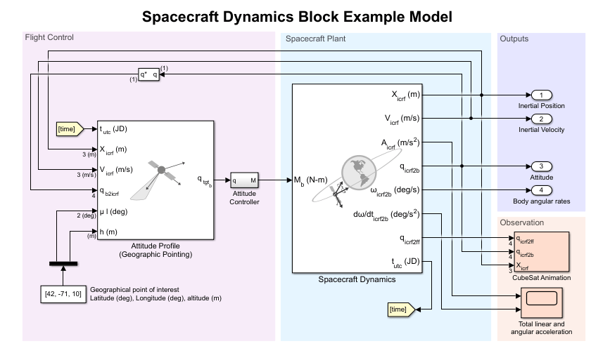
The satellite is in a near-circular, low Earth orbit (LEO) at an altitude of approximately 500km. For orbit propagation, we use Earth spherical harmonic model EGM2008 with degree set to 120. We use Earth orientation parameter data from default file aeroiersdata.mat, which is included in the Aerospace Toolbox. The satellite mass properties are fixed, with mass equal to 1kg and a simple inertia tensor of . The mission start date is January 1, 2020, 12:00:00, and runs for 6 hours.
To provide attitude control, we use the Attitude Profile block from the Aerospace Blockset, connected to a simple PD controller. Our desired attitude aligns the satellite body-z axis with geographic coordinates at an altitude of 10m. For our secondary constraint, we align the body-x axis with the y-axis of the local-vertical, local-horizontal (LVLH) frame. In a (near) circular orbit, the y-axis of the LVLH frame points in the direction of the travel of the satellite. This alignment keeps our satellite pointing "forward" as we sweep over our geographic point of interest on each pass. You can also use the Attitude Profile block to align the satellite with Earth nadir, a different geographical location, a celestial body from JPL Ephemerides DE405, or any custom vector provided as an input to the block.
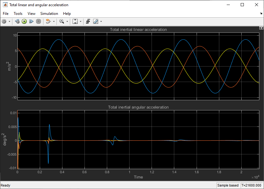
The model has linear and angular acceleration outputs from the Spacecraft Dynamics block connected to a scope. Do not use these outputs as part of a simulation loop. Our inertial linear acceleration is smooth throughout the simulation, which is expected as we are not performing any translational (delta-V) maneuvers. In the angular acceleration plot, we observe that passes over our geographical point of interest coincide with larger acceleration values. When we pass directly over the point of interest (the first pass), the change in angular velocity required is much larger than when we pass over the point of interest at a shallower angle (subsequent passes).
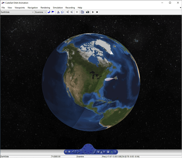
Simulation playback animation is enabled in the example model using a satelliteScenario object visualized in the Satellite Scenario Viewer. The Satellite Scenario Playback block configures the scenario for visualization, and the block's StopFcn creates the scenario object and launches the viewer. Use the block dialog to display coordinate axis triads (Body frame), 3D satellite models, or enable a camera field of view in the viewer. Use the satellite scenario object exSatScenario created in the base workspace after each run to add additional satellites, ground stations, or platforms and perform mission analysis including line of sight access and eclipse analysis.
Block Equations
We now explore the equations implemented by the block to better understand how the block calculates output values at each timestep.
Translational System Equations
Translation motion is governed by:
where:
is the user-defined acceleration provided to the block external acceleration input port.
is the body force in the Body coordinate system, with respect to the ICRF frame (inertial).
is the current spacecraft mass (see mass equations below).
is the transformation from the rotating body-fixed coordinate system to the inertial ICRF coordinate system, resulting in the following acceleration contribution from forces:
where:
is the force provided to the block body forces input port.
is the relative velocity at which the mass flow () is ejected from or added to the body in the Body coordinate system, with respect to the Body frame.
is the passive quaternion rotation of the body with respect to the inertial ICRF frame.
is the angular velocity of the body with respect to the inertial ICRF frame.
Rotational System Equations
Rotational motion is governed by:
where:
is the inertia tensor with respect to the body origin (see Mass section below).
is the rate of change of the inertia tensor (see Mass section below).
is the 3x3 matrix inverse.
is the total body moment, comprised of the value provided to the block body moments input port and the internally calculated gravity gradient torque:
is the standard gravitation parameter of the central body.
The integration of the rate of change of the quaternion vector is calculated as:
The Aerospace Toolbox and Aerospace Blockset use quaternions that are defined using the scalar-first convention.
Mass
The mass , mass flow rate , inertia tensor , and rate of change of the inertia tensor used in the above system equations are determined depending on the current parameter selections in the Mass tab.
Fixed
This option models the spacecraft as a fixed mass rigid body.
is the mass provided for parameter Mass on the Mass tab.
equals zero.
is the inertia tensor provided for parameter Inertia tensor on the Mass tab.
equals zero.
Simple variable
This option models the spacecraft as a simple, variable-mass rigid body.
is the mass bounded between and , calculated by integrating .
is provided to the block's dm/dt input port.
Custom variable
This option models the spacecraft as a variable-mass rigid body, providing the highest level of configurability.
is provided to the block m input port.
is provided to the block dm/dt input port when Include mass flow relative velocity is enabled, otherwise the value is not needed by the system equations.
is provided to the block I input port.
is provided to the block dI/dt input port.
Central Body Gravity
The acceleration due to central body gravity is calculated depending on the current parameter selections in the Central Body tab. For gravity models that include nonspherical acceleration terms (Oblate ellipsoid (J2) and Spherical harmonics), nonspherical gravity is computed in the fixed-frame coordinated system (ITRF, in the case of Earth). Numerical integration, however, is always performed in the inertial ICRF coordinate system. Therefore, at each timestep, position and velocity states are transformed into the fixed-frame, nonspherical gravity is calculated in the fixed-frame, and the resulting acceleration is then transformed into the inertial frame. In the inertial frame, the resulting acceleration is summed with the other acceleration terms and double-integrated to find velocity and position.
Point-mass (available for all central bodies)
This option treats the central body as a point mass, including only the effects of spherical gravity using Newton's law of universal gravitation.
Oblate ellipsoid (J2) (available for all central bodies)
In addition to spherical gravity, this option includes the perturbing effects of the second-degree, zonal harmonic gravity coefficient, , accounting for the oblateness of the central body. accounts for most of central body gravitational departure from a perfect sphere.
where:
given the partial derivatives in spherical coordinates:
where:
and are the satellite geocentric latitude and longitude
and are associated Legendre functions
is the central body equatorial radius
converts fixed-frame position, velocity, and acceleration into the ICRF coordinate system with origin at the center of the central body, accounting for centrifugal and Coriolis acceleration. For more information about the fixed and inertial coordinate systems used for each central body, see the Coordinate Frames section of the Spacecraft Dynamics block reference page. The fixed-frame coordinate frame used for Earth is the ITRF.
Spherical Harmonics (available for Earth, Moon, Mars, Custom)
This option adds increased fidelity by including higher-order perturbation effects accounting for zonal, sectoral, and tesseral harmonics. For reference, the second-degree zeroth order zonal harmonic is . The Spherical Harmonics model accounts for harmonics up to max degree , which varies by central body and geopotential model.
where:
given the following partial derivatives in spherical coordinates:
are associated Legendre functions.
and are the un-normalized harmonic coefficients.
Atmospheric Drag
where:
- Spacecraft mass used by atmospheric drag calculation.
- Coefficient of drag assuming that it is dimensionless.
- Atmospheric density.
- Area normal to , where
- Velocity relative to atmosphere where is the central body angular velocity.
Third Body Gravity
where:
- Gravitational parameter of the third body.
- Vector from the satellite to the third body.
- Position vector of third body with respect to the central body.
Solar Radiation Pressure
where:
- Mass of the spacecraft.
- Eclipse shadow function.
- Spacecraft coefficient of reflectivity.
- Spacecraft solar radiation pressure area.
- Solar radiation pressure at a distance of AU from the sun.
- Mean distance from the Sun to Earth (1AU).
- Vector from the satellite to the Sun origin.
References
[1] Vallado, David. Fundamentals of Astrodynamics and Applications, 4th ed. Hawthorne, CA: Microcosm Press, 2013.
[2] Vepa, R., Dynamics and Control of Autonomous Space Vehicles and Robotics, University Printing House, New York, NY,USA, 2019.
[3] Stevens, B. L., F. L. Lewis, Aircraft Control and Simulation, Second Edition, John Wiley & Sons, Hoboken NJ, 2003.
[4] Gottlieb, R. G., "Fast Gravity, Gravity Partials, Normalized Gravity, Gravity Gradient Torque and Magnetic Field: Derivation, Code and Data," Technical Report NASA Contractor Report 188243, NASA Lyndon B. Johnson Space Center, Houston, Texas, February 1993.
[5] Konopliv, A. S., S. W. Asmar, E. Carranza, W. L. Sjogen, D. N. Yuan., "Recent Gravity Models as a Result of the LunarProspector Mission, Icarus", Vol. 150, no. 1, pp 1–18, 2001.
[6] Lemoine, F. G., D. E. Smith, D.D. Rowlands, M.T. Zuber, G. A. Neumann, and D. S. Chinn, "An improved solution of the gravity field of Mars (GMM-2B) from Mars Global Surveyor", Journal Of Geophysical Research, Vol. 106, No. E10, pp 23359-23376, October 25, 2001.
[7] Seidelmann, P.K., Archinal, B.A., A’hearn, M.F. et al. Report of the IAU/IAG Working Group on cartographic coordinates and rotational elements: 2006. Celestial Mech Dyn Astr 98, 155–180 (2007).
[8] Standish, E. M., "JPL Planetary and Lunar Ephemerides, DE405/LE405", JPL IOM 312.F-98-048, Pasadena, CA,1998.