Aircraft Design Optimization with the Fixed-Wing Object
This example shows how to optimize aircraft size and geometry using the Aero.FixedWing object to enforce static stability constraints.
Aircraft Design Objective
The aircraft is designed for the Regular Class of the Society of Automotive Engineers (SAE) Aero Design competition. In this competition, the teams aim to maximize their flight score, which is calculated as follows.
where:
Number of spherical payloads
Weight of boxed payloads [kg]
Wingspan [m]
Length of cargo bay [m]
All these variables are essentially continuous, except for , which is discrete. This variable complicates the problem formulation. Thus, only the case is considered.
Optimization Constraints
The competition imposes constraints that are important to the optimization:
The gross takeoff weight cannot exceed 24.9 kg.
The wingspan cannot exceed 3 m.
The takeoff distance cannot exceed 30.5 m.
Beyond this, impose additional requirements to favor a conventional design:
The aircraft must be statically stable.
No interference is allowed between the wing, tail, payload, avionics, and landing gear.
The wing and horizontal tail aspect ratios must be high enough for Prandtl lifting-line theory to be valid.
The wing and tail aspect ratios must be low enough to guarantee structural strength.
The wing aerodynamic center must be in the front half of the fuselage.
The static margin must be constrained so the aircraft pitches easily, without being too sensitive to disturbances.
Additionally, all optimization variables are physical quantities and must be positive.
Assumptions
To further simplify the formulation, assume the wing has a simple geometry, with:
No dihedral
No sweep
No wing twist
No wing tip devices
incidence angle
Wing Z-location at fuselage centerline
The design also omits the effect of any control surfaces and the propulsion system.
Optimization Problem Formulation
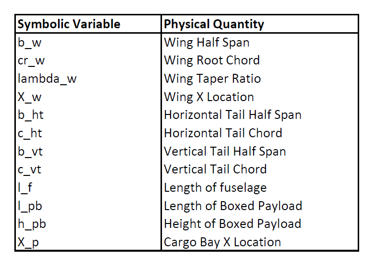
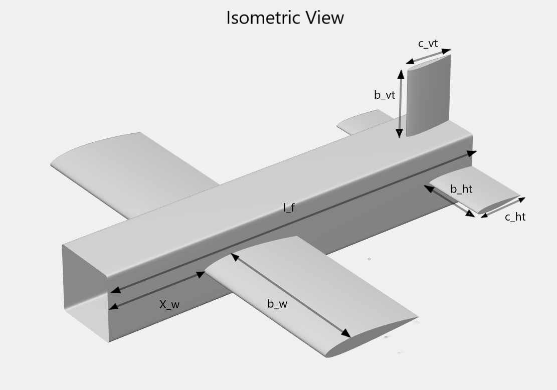
To optimize the aircraft geometry, use the problem-based approach. Start by defining problem constants and the optimization variables using the helper function initializeAircraft, which is included with this example. Organize these variables into six structures: aircraft, wing, hTail, vTail, fuselage, and payload. See a list of the optimization variables and their physical representation below.
[aircraft, wing, fuselage, hTail, vTail, payload, initialValues] = initializeAircraft;


Set up the design optimization problem
Define an empty optimization problem and set maximization as its objective.
designprob = optimproblem('ObjectiveSense','maximize');
Estimate lift and drag coefficients for the wing, tail, and fuselage.
[aircraft, wing, fuselage, hTail, vTail, designprob] = ...
    addAerodynamics(aircraft, wing, fuselage, hTail, vTail, designprob);
Use the component build-up method to formulate the aircraft mass and introduce the gross takeoff weight constraint.
[aircraft, wing, fuselage, hTail, vTail, payload, designprob] = ...
    addWeightAndSizing(aircraft, wing, fuselage, hTail, vTail, payload, designprob);
To compute the static stability derivatives, create an instance of the Aero.FixedWing and Aero.FixedWing.State objects.
[myAircraft, CruiseState] = createFixedWing(aircraft.Mass, wing, hTail, initialValues);
Add the static stability constraints to the optimization problem. The following ten derivatives play a major role in an aircraft response to external disturbances and so are used as constraints: , , , , , , , , , .
To compute these derivatives, the addStability function calculates all aerodynamic coefficients and the mass moment of inertia matrix for the aircraft. With this information, use the staticStability method of the Aero.FixedWing object to obtain the ten stability derivatives.
[aircraft, wing, vTail, designprob] = ...
    addStability(aircraft, wing, fuselage, hTail, vTail, payload, designprob, myAircraft, CruiseState);
Estimate takeoff performance and include maximum takeoff distance, or ground roll, constraint.
[aircraft,designprob] = addPerformance(aircraft, wing.PlanformArea, wing.MeanChord, designprob);
Write the objective function to match the SAE Aero Design Regular Class flight score. Units are converted to metric.
designprob.Objective = 3*(2+2.2*payload.Boxed.Mass)/((2*wing.HalfSpan+payload.Length));
Set options for optimization solver
Let the solver run to completion by setting the maximum number of function evaluations and iterations to infinity.
options = optimoptions(designprob);
options.MaxFunctionEvaluations = Inf;
options.MaxIterations = Inf;
If steps become too small, stop the optimization early.
options.StepTolerance = 1e-4;
Have the solver automatically plot the results of each iteration while it runs.
options.PlotFcn = {'optimplotconstrviolation', 'optimplotfvalconstr'};Use a parallel pool to speed up the computation.
options.UseParallel = true;
options.Display = 'off';
Solve the optimization problem
Solving the problem returns both the maximum flight score for this design and the corresponding values of the 12 optimization variables.
[finalValues, maxScore] = solve(designprob, initialValues, 'Options', options);Starting parallel pool (parpool) using the 'Processes' profile ... 08-Oct-2024 14:18:18: Job Queued. Waiting for parallel pool job with ID 1 to start ... Connected to parallel pool with 6 workers.

maxScore
maxScore =
18.7541
The solution quickly gets close to the optimal value, and most steps are spent on the final improvements. Due to the nonlinearity of this problem, the solution might not be globally optimal. Different initial conditions might result in a predicted flight score better than 18.754. The optimized design has a final geometry with a large tapered wing and a moderately sized tail placed at the end of the fuselage.
References
[1] Roskam, Jan. Airplane Design, Part VI: Preliminary Calculation of Aerodynamic, Thurst and Power Characteristics. Lawrence, KA: DAR Corporation, 2008.
[2] Roskam, Jan. Airplane Flight Dynamics and Automatic Flight Controls, Part I. Lawrence, KA: DAR Corporation, 2003.
[3] Raymer, Daniel P. Aircraft Design: A Conceptual Approach. Washington, DC: AIAA, 1992.