Main Content

rainpl

RF signal attenuation due to rainfall using ITU model

Description

L = rainpl(range,freq,rainrate) returns the signal attenuation, L, due to rain with a long-term statistical rain rate. In this syntax, attenuation is a function of signal path length, range, signal frequency, freq, and rain rate, rainrate. The path elevation angle and polarization tilt angles are assumed to be zero.

The rainpl function applies the International Telecommunication Union (ITU) rainfall attenuation model to calculate path loss of signals propagating in a region of rainfall [1]. The function applies when the signal path is contained entirely in a uniform rainfall environment. Rain rate does not vary along the signal path. The attenuation model applies only for frequencies at 1–1000 GHz.

example

L = rainpl(range,freq,rainrate,elev) also specifies the elevation angle, elev, of the propagation path.

example

L = rainpl(range,freq,rainrate,elev,tau) also specifies the polarization tilt angle, tau, of the signal.

example

L = rainpl(range,freq,rainrate,elev,tau,pct) also specifies the specified percentage of time, pct. pct is a scalar in the range of 0.001–1, inclusive. The attenuation, L, is computed from a power law using the long-term statistical 0.01% rain rate (in mm/h).

Examples

collapse all

Compute the signal attenuation due to rainfall for a 20 GHz signal over a distance of 10 km in light and heavy rain.

Propagate the signal in a light rainfall of 1 mm/hr.

rr = 1.0;
L = rainpl(10000,20.0e9,rr)
L = 
1.3009

Propagate the signal in a heavy rainfall of 10 mm/hr.

rr = 10.0;
L = rainpl(10000,20.0e9,rr)
L = 
8.1584

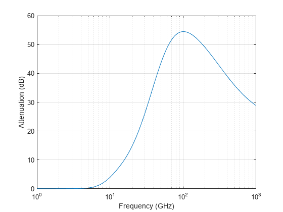
Plot the signal attenuation due to a 20 mm/hr statistical rainfall for signals in the frequency range from 1 to 1000 GHz. The path distance is 10 km.

rr = 20.0;
freq = [1:1000]*1e9;
L = rainpl(10000,freq,rr);
semilogx(freq/1e9,L)
grid
xlabel('Frequency (GHz)')
ylabel('Attenuation (dB)')

Figure contains an axes object. The axes object with xlabel Frequency (GHz), ylabel Attenuation (dB) contains an object of type line.

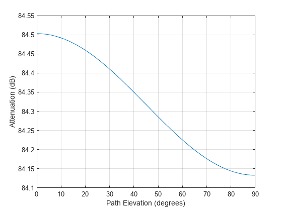
Compute the signal attenuation due to heavy rain as a function of elevation angle. Elevation angles vary from 0 to 90 degrees. Assume a path distance of 100 km and a signal frequency of 100 GHz.

Set the rain rate to 10 mm/hr.

rr = 10.0;

Set the elevation angles, frequency, range.

elev = [0:1:90];
freq = 100.0e9;
rng = 100000.0*ones(size(elev));

Compute and plot the loss.

L = rainpl(rng,freq,rr,elev);
plot(elev,L)
grid
xlabel('Path Elevation (degrees)')
ylabel('Attenuation (dB)')

Figure contains an axes object. The axes object with xlabel Path Elevation (degrees), ylabel Attenuation (dB) contains an object of type line.

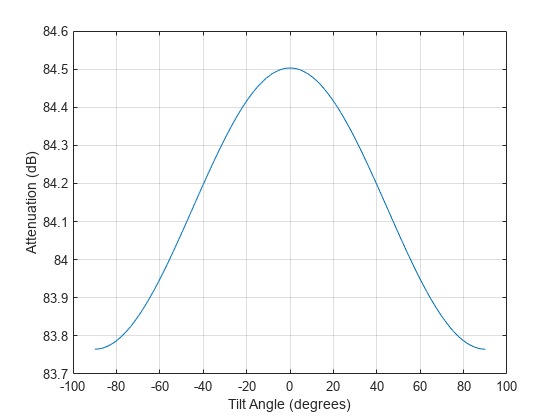
Compute the signal attenuation due to heavy rainfall as a function of the polarization tilt angle. Assume a path distance of 100 km, a signal frequency of 100 GHz, and a path elevation angle of 0 degrees. Set the rainfall rate to 10 mm/hour. Plot the signal attenuation versus polarization tilt angle.

Set the polarization tilt angle to vary from -90 to 90 degrees.

tau = -90:90;

Set the elevation angle, frequency, path distance, and rain rate.

elev = 0;
freq = 100.0e9;
rng = 100e3*ones(size(tau));
rr = 10.0;

Compute and plot the attenuation.

L = rainpl(rng,freq,rr,elev,tau);
plot(tau,L)
grid
xlabel('Tilt Angle (degrees)')
ylabel('Attenuation (dB)')

Figure contains an axes object. The axes object with xlabel Tilt Angle (degrees), ylabel Attenuation (dB) contains an object of type line.

Input Arguments

collapse all

Signal path length in meters, specified as a nonnegative real-valued scalar, or as a M-by-1 or 1-by-M vector.

Example: [13000.0,14000.0]

Signal frequency in Hz, specified as a positive real-valued scalar, or as a nonnegative N-by-1 or 1-by-N vector. Frequencies must lie in the range 1–1000 GHz.

Example: [1400.0e6,2.0e9]

Long-term statistical rain rate, in mm/h, specified as a nonnegative real-valued scalar. The long-term statistical rain rate is the rain rate that is exceeded 0.01% of the time. You can adjust the percent of time using the pct argument.

Example: 1.5

Signal path elevation angle, in degrees, specified as a real-valued scalar, an M-by-1 vector, or a 1-by- M vector. Units are in degrees between –90° and 90°. If elev is a scalar, all propagation paths have the same elevation angle. If elev is a vector, its length must match the dimension of range and each element in elev corresponds to a propagation range in range.

Example: [0,45]

Tilt angle of the signal polarization ellipse, in degrees, specified as a real-valued scalar, or as an M-by-1 or 1-by- M vector. Units are in degrees between –90° and 90°. If tau is a scalar, all signals have the same tilt angle. If tau is a vector, its length must match the dimension of range. In that case, each element in tau corresponds to a propagation path in range.

The tilt angle is defined as the angle between the semi-major axis of the polarization ellipse and the x-axis. Because the ellipse is symmetrical, a tilt angle of 100° corresponds to the same polarization state as a tilt angle of -80°. Thus, the tilt angle need only be specified between ±90°.

Example: [45,30]

Exceedance percentage of rainfall, in %, specified as a positive scalar between 0.001 and 1. The long-term statistical rain rate is the rain rate that is exceeded pct of the time.

Data Types: double

Output Arguments

collapse all

Signal attenuation in dB, returned as a real-valued M-by-N matrix. Each matrix row represents a different path where M is the number of paths. Each column represents a different frequency where N is the number of frequencies.

More About

collapse all

Rainfall Attenuation Model

This model calculates the attenuation of signals that propagate through regions of rainfall. Rain attenuation is a dominant fading mechanism and can vary from location-to-location and from year-to-year.

Electromagnetic signals are attenuated when propagating through a region of rainfall. Rainfall attenuation is computed according to the ITU rainfall model Recommendation ITU-R P.838-3: Specific attenuation model for rain for use in prediction methods. The model computes the specific attenuation (attenuation per kilometer) of a signal as a function of rainfall rate, signal frequency, polarization, and path elevation angle. The specific attenuation, ɣR, is modeled as a power law with respect to rain rate

γR=kRα,

where R is rain rate. Units are in mm/hr. The parameter k and exponent α depend on the frequency, the polarization state, and the elevation angle of the signal path. The specific attenuation model is valid for frequencies from 1–1000 GHz.

To compute the total attenuation for narrowband signals along a path, the function multiplies the specific attenuation by the an effective propagation distance, deff. Then, the total attenuation is L = deffγR.

The effective distance is the geometric distance, d, multiplied by a scale factor

r=10.477d0.633R0.010.073αf0.12310.579(1exp(0.024d))

where f is the frequency. The article Recommendation ITU-R P.530-17 (12/2017): Propagation data and prediction methods required for the design of terrestrial line-of-sight systems presents a complete discussion for computing attenuation.

The rain rate, R, used in these computations is the long-term statistical rain rate, R0.01. This is the rain rate that is exceeded 0.01% of the time. The calculation of the statistical rain rate is discussed in Recommendation ITU-R P.837-7 (06/2017): Characteristics of precipitation for propagation modelling. This article also explains how to compute the attenuation for other percentages from the 0.01% value.

You can also apply the attenuation model to wideband signals. First, divide the wideband signal into frequency subbands and apply attenuation to each subband. Then, sum all attenuated subband signals into the total attenuated signal.

References

[1] Radiocommunication Sector of International Telecommunication Union. Recommendation ITU-R P.838-3: Specific attenuation model for rain for use in prediction methods. 2005.

[2] Radiocommunication Sector of International Telecommunication Union. Recommendation ITU-R P.530-17: Propagation data and prediction methods required for the design of terrestrial line-of-sight systems. 2017.

[3] Recommendation ITU-R P.837-7: Characteristics of precipitation for propagation modelling

[4] Seybold, J. Introduction to RF Propagation. New York: Wiley & Sons, 2005.
Extended Capabilities