pattern
Display antenna radiation pattern in Site Viewer
Description
pattern( displays the 3-D antenna
radiation pattern for the specified transmitter site in the current Site Viewer.
By default, the function calculates the pattern using the frequency stored in
tx)TransmitterFrequency property of the transmitter site.
The antenna gain (dBi) in a particular direction determines the color of the
pattern.
pattern(___,
displays the 3-D radiation pattern with additional options specified by
name-value arguments.Name=Value)
Examples
Define and visualize the radiation pattern of a single transmitter site.
tx = txsite;
pattern(tx)

Design a receiver site using a dipole antenna at a height of 30 meters.
d = dipole;
rx = rxsite("Name","Mathworks Lakeside", ...
    "Latitude",42.30321,"Longitude",-71.3764, ...
    "Antenna",d,"AntennaHeight",30);
Visualize the pattern of the receiver site at 75 MHz.
pattern(rx,75e6)

Create a directional antenna.
yagiAntenna = design(yagiUda,4.5e9);
yagiAntenna.Tilt = 90;
yagiAntenna.TiltAxis = "y";
Create transmitter and receiver sites at a frequency of 4.5 GHz. Use the Yagi antenna as the transmitter antenna. Design a dipole at 4.5 GHz and use this as the receiver antenna.
fq = 4.5e9;
tx = txsite(Name="MathWorks",Latitude=42.3001,Longitude=-71.3503, ...
      Antenna=yagiAntenna,AntennaAngle=90,AntennaHeight=30, ...
      TransmitterFrequency=fq,TransmitterPower=10);
rx = rxsite(Antenna=design(dipole,fq));
Position the receiver 200 meters from the transmitter.
[lat,lon] = location(tx,200,90);
rx.Latitude = lat;
rx.Longitude = lon;
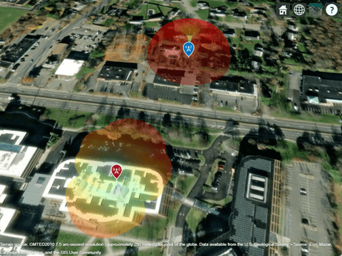
Display both transmitter and receiver patterns. Zoom out so you can see both of the patterns.
pattern(tx,Transparency=0.2)
pattern(rx,fq)
Import and view an STL file. The file models a small conference room with one table and four chairs.
viewer = siteviewer("SceneModel","conferenceroom.stl");
Design an inverted-F antenna mounted over a rectangular ground plane that resonates at 2.4 GHz. Create a transmitter site that uses the antenna. Specify the position using Cartesian coordinates in meters.
ant = design(invertedF,2.4e9);
ant.Tilt = 180;

tx = txsite("cartesian", ...
    "AntennaPosition",[0; 0; 2.1], ...
    "Antenna",ant);
Visualize the pattern of the site. Specify the size of the pattern plot as 0.4 meters.
pattern(tx,"Transparency",0.6,"Size",0.4)
Pan by left-clicking, zoom by right-clicking or by using the scroll wheel, and rotate the visualization by clicking the middle button and dragging or by pressing Ctrl and left-clicking and dragging.
![]()
Input Arguments
Name-Value Arguments
Specify optional pairs of arguments as
Name1=Value1,...,NameN=ValueN, where Name is
the argument name and Value is the corresponding value.
Name-value arguments must appear after other arguments, but the order of the
pairs does not matter.
Example: pattern(tx,Size=2) specifies the size of the pattern
plot.
Before R2021a, use commas to separate each name and value, and enclose
Name in quotes.
Example: pattern(tx,'Size',2) specifies the size of the pattern
plot.
Transparency of the pattern plot, specified as a scalar the range [0,
1], where 0 is completely transparent and
1 is completely opaque.
Data Types: double
Colormap for the pattern plot, specified as a colormap name or as an M-by-3 array of RGB triplets that define M individual colors.
You can view a colorbar that indicates the mapping of gain values into the colormap by clicking the transmitter or receiver site.
This table lists the colormap names.
| Colormap Name | Color Scale |
|---|---|
|
|
|
|
|
|
|
|
|
|
|
|
|
|
|
|
|
|
|
|
|
|
|
|
|
|
|
|
|
|
|
|
|
|
|
|
|
|
|
|
|
|
|
|
Data Types: double
Resolution of 3-D map, specified as "low",
"medium", or "high". The
resolution controls the visual quality and the time required to plot the
pattern. The value "low" corresponds to the fastest
and the least detailed pattern.
Data Types: double
Map for visualization of surface data, specified as a siteviewer object.1
Data Types: char | string
Version History
Introduced in R2018b
1 Alignment of boundaries and region labels are a presentation of the feature provided by the data vendors and do not imply endorsement by MathWorks®.