Antenna Array Beam Scanning Visualization on a Map
This example shows how to visualize the changing pattern and coverage map of an antenna array as it scans a sweep of angles. The antenna array is created using Antenna Toolbox™ and Phased Array System Toolbox™. The array is designed to be directional and radiate in the xy-plane to generate a maximum coverage region in the geographic azimuth. Transmitter and receiver sites are created and shown on a map, and the pattern and coverage map are displayed as the antenna array is steered.
Design a Reflector-Backed Dipole Antenna Element
Use Antenna Toolbox to design a reflector-backed dipole antenna element. Design the element and its exciter for 10 GHz, and specify tilt to direct radiation in the xy-plane, which corresponds to the geographic azimuth.
% Design reflector-backed dipole antenna element
fq = 10e9; % 10 GHz
myelement = design(reflector,fq);
myelement.Exciter = design(myelement.Exciter,fq);

% Tilt antenna element to radiate in xy-plane, with boresight along x-axis
myelement.Tilt = 90;
myelement.TiltAxis = "y";
myelement.Exciter.Tilt = 90;
myelement.Exciter.TiltAxis = "y";
Create a 7-by-7 Rectangular Antenna Array
Use Phased Array System Toolbox to create a 7-by-7 rectangular array from the antenna element. Specify the array normal to direct radiation in the x-axis direction.
% Create 7-by-7 antenna array
nrow = 7;
ncol = 7;
myarray = phased.URA("Size",[nrow ncol],"Element",myelement);

% Define element spacing to be half-wavelength at 10 GHz, and specify
% array plane as yz-plane, which directs radiation in x-axis direction
lambda = physconst("lightspeed")/fq;
drow = lambda/2;
dcol = lambda/2;
myarray.ElementSpacing = [drow dcol];
myarray.ArrayNormal = "x";

% Display radiation pattern
f = figure;
az = -180:1:180;
el = -90:1:90;
pattern(myarray,fq,az,el)

Create Transmitter Site at Washington Monument
Create a transmitter site at the Washington Monument in Washington, DC, using the antenna array. The transmitter frequency matches the antenna's design frequency, and the transmitter output power is 1 W. Set antenna height to 169 m, which is the height of the monument.
tx = txsite("Name","Washington Monument",...
    "Latitude",38.88949, ...
    "Longitude",-77.03523, ...
    "Antenna",myarray,...
    "AntennaHeight",169', ...
    "TransmitterFrequency",fq,...
    "TransmitterPower",1);
Show Transmitter Site on a Map
Launch Site Viewer and show the transmitter site, which centers the view at the Washington Monument. The default map shows satellite imagery, and the site marker is shown at the site's antenna height.
if isvalid(f)
    close(f)
end
viewer = siteviewer;
show(tx)

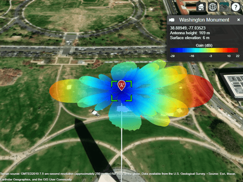
Show Antenna Radiation Pattern on a Map
Visualize the orientation of the antenna by showing the radiation pattern in Site Viewer.
pattern(tx)
Select the site marker to view the color legend of the pattern.

Create Receiver Sites
Create an array of receiver sites in the Washington, DC, area. These are used as place markers for sites of interest to assess the coverage of the transmitter site.
% Define names for receiver sites
rxNames = [...
    "Brentwood Hamilton Field" ...
    "Nationals Park" ...
    "Union Station" ...
    "Georgetown University" ...
    "Arlington Cemetery"];

% Define coordinates for receiver sites
rxLocations = [...
    38.9080 -76.9958; ...
    38.8731 -77.0075; ...
    38.8976 -77.0062; ...
    38.9076 -77.0722; ...
    38.8783 -77.0685];

% Create array of receiver sites. Each receiver has a sensitivity of -75 dBm.
rxs = rxsite("Name",rxNames, ...
    "Latitude",rxLocations(:,1), ...
    "Longitude",rxLocations(:,2), ...
    "ReceiverSensitivity",-75);
Show receiver sites on a map.
show(rxs)
Set the map imagery using the Basemap property. Alternatively, open the map imagery picker in Site Viewer by clicking the second button from the right. Select "Streets" to see streets and labels on the map.
viewer.Basemap = "streets";
Scan the Array and Update the Radiation Pattern
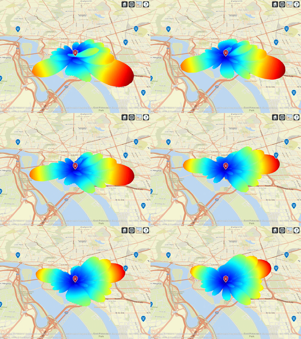
Scan the antenna beam by applying a taper for a range of angles. For each angle, update the radiation pattern in Site Viewer. This approach of scanning the beam produces different patterns than physically rotating the antenna, as could be achieved by setting AntennaAngle of the transmitter site. This step is used to validate the orientation of the antenna's main beam.
% Get the starting array taper
startTaper = myarray.Taper;

% Define angles over which to perform sweep
azsweep = -30:10:30;

% Set up tapering window and steering vector
N = nrow*ncol;
nbar = 5;
sll = -20;
sltaper = taylorwin(N,nbar,sll)';
steeringVector = phased.SteeringVector("SensorArray",myarray);

% Sweep the angles and show the antenna pattern for each
for az = azsweep
    sv = steeringVector(fq,[az; 0]);
    myarray.Taper = sltaper.*sv';

    % Update the radiation pattern. Use a larger size so the pattern is visible among the antenna sites.
    pattern(tx, "Size", 2500,"Transparency",1);
end

Display Transmitter Coverage Map
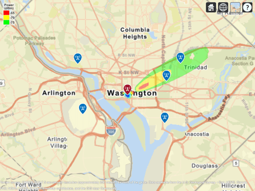
Define three signal strength levels and corresponding colors to display on the coverage map. Each color is visible where the received power for a mobile receiver meets the corresponding signal strength. The received power includes the total power transmitted from the rectangular antenna array.
The default orientation of the transmitter site points the antenna x-axis east, so that is the direction of maximum coverage.
% Reset the taper to the starting taper
myarray.Taper = startTaper;

% Define signal strength levels (dBm) and corresponding colors
strongSignal = -65;
mediumSignal = -70;
weakSignal = -75;
sigstrengths = [strongSignal mediumSignal weakSignal];
sigcolors = ["red" "yellow" "green"];

% Show the tx pattern
pattern(tx,"Size",500)

% Display coverage map out to 6 km
maxRange = 6000;
coverage(tx, ...
    "SignalStrengths",sigstrengths, ...
    "Colors",sigcolors, ...
    "MaxRange",maxRange)

The coverage map shows no coverage at the transmitter site and a couple of pockets of coverage along the boresight direction before the main coverage area. The radiation pattern provides insight into the coverage map by showing how the antenna power projects onto the map locations around the transmitter.

Scan the Array and Update the Coverage Display
Scan the antenna beam by applying a taper for a range of angles. For each angle, update the coverage map. This method of beamscanning is the same method used above. The final map includes two receiver sites of interest within the coverage region.
% Repeat the sweep but show the pattern and coverage map
for az = azsweep
    % Calculate and assign taper from steering vector
    sv = steeringVector(fq,[az; 0]);
    myarray.Taper = sltaper.*sv';

    % Update the tx pattern
    pattern(tx,"Size",500)

    % Update coverage map
    coverage(tx, ...
        "SignalStrengths",sigstrengths, ...
        "Colors",sigcolors, ...
        "MaxRange",maxRange)
end

See Also
Functions
Objects
siteviewer|txsite|rxsite|phased.URA(Phased Array System Toolbox) |phased.SteeringVector(Phased Array System Toolbox)