Design PIFA for WLAN Wi-Fi Applications
This example discusses the PIFA designed for Wi-Fi applications [1]. The Planar Inverted-F Antenna (PIFA) is basically a grounded patch antenna with the patch length of /4 (open-short microstrip resonator) instead of the conventional /2 for the patch antenna (open-open microstrip resonator). It typically consists of a ground plane, a top patch grounded at one end, and a coaxial probe feeding the top patch. The PIFA is commonly used in mobile communications since it has low manufacturing cost, smaller than the patch antenna size, and a relatively simple structure. In addition it also has reduced backward radiation towards user's head. However, the patch antenna has better polarization purity. Hundreds of PIFA varieties have recently been developed for mobile phones.
Design Parameters
The design parameters for this antenna are length, width, and height of the top patch, as well as the location of the feed probe. The shorting strip is always located at one patch edge; its length is always the edge length. Start the design process with antenna dimensions initialized below. The patch length is chose to be quarter wavelength at the upper frequency of the band (2.5 GHz).
patchLength = 30e-3;
patchWidth = 20e-3;
patchHeight = 10e-3;
lengthgp = 35e-3;
widthgp = 35e-3;
feedoffset = [-patchLength/2+ 5e-3 0];
Create Planar Inverted-F Antenna
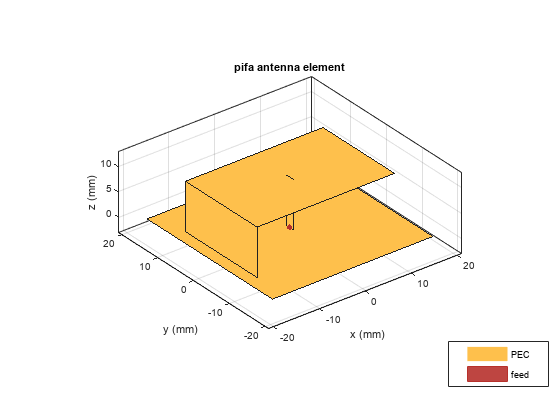
Create a PIFA using the parameters defined above. The feed offset is so specified that the feed is 5mm away from the shorted patch edge. The strip feed width corresponds to a wire with the radius of 1mm.
ant = pifa(Length=patchLength, Width=patchWidth, Height=...
    patchHeight, GroundPlaneLength=lengthgp, GroundPlaneWidth=...
    widthgp, ShortPinWidth=patchWidth, FeedOffset=feedoffset);
figure
show(ant)

Design for WLAN Applications
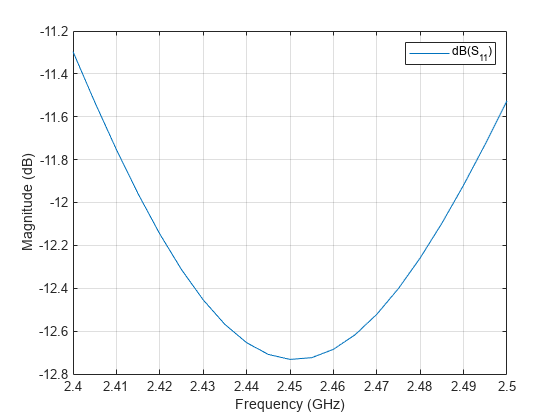
This section discusses design of a compact PIFA with a suitable bandwidth for wireless application in the Wi-Fi band. The bandwidth is defined as the frequency band in which VSWR is less than 2:1 which approximately corresponds to a -10 dB or lower reflection coefficient. This means that 10% or less of the incident power is reflected back to the generator.
freq = linspace(2.4e9, 2.5e9, 21);
s1 = sparameters(ant,freq);
S11Fig1 = figure;
rfplot(s1);
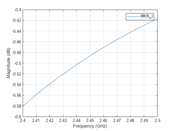
From the plot above, it follows that the antenna is not matched. The antenna design needs to be changed to ensure that the reflection coefficient is less than -10 dB over the frequency range of interest.
Vary Antenna Feed Location
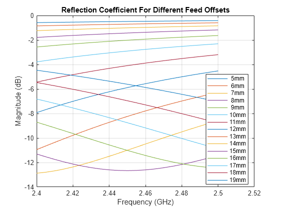
A simple and efficient way to provide impedance match for both PIFA and patch antennas is to move the feed location. The feed is typically moved along the resonating length of the patch and find the position where the best match is achieved. Use the FeedOffset property for this purpose and plot the reflection coefficient for every feed location.
feedoffsetx = 5e-3:1e-3:19e-3;
S11 = zeros(numel(freq), numel(feedoffsetx));
for m =1:length(feedoffsetx)
    feedoffset  = [-patchLength/2 + feedoffsetx(m) 0];
    ant.FeedOffset = feedoffset;
    S = sparameters(ant,freq);
    S11(:,m) = 20*log10(abs(S.Parameters));
end
S11Fig2 = figure;
plot(freq./1e9, S11);
legend(strcat(num2str(feedoffsetx'.*1e3), "mm"), location="Best");
grid on;
title("Reflection Coefficient For Different Feed Offsets");
xlabel("Frequency (GHz)");
ylabel("Magnitude (dB)");
Choose Best Design
From the reflection coefficient plots it can be observed that the feed offset of 15 mm provides the best match. Update the feed offset and visualize the new antenna structure. The feed is now located closer to the patch center.
ant.FeedOffset = [-patchLength/2 + 15e-3 0];
figure
show(ant)
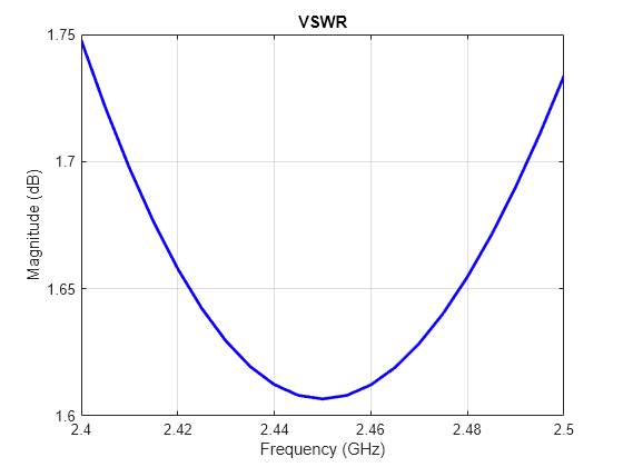
Also plot the reflection coefficient and VSWR for the optimal antenna design.
s2 = sparameters(ant,freq);
S11Fig3 = figure;
rfplot(s2);
VSWRFig = figure;
vswr(ant, freq);
Reference
[1] G. M. Khanal,"Design of a Compact PIFA for WLAN Wi-Fi Wireless Applications," Int. J. of Engineering Research and Development, www.ijerd.com Vol. 8, Issue 7, Sept. 2013, pp. 13-18, e-ISSN:2278-067X, p-ISSN: 2278-800X. Available online at:http://www.ijerd.com/paper/vol8.issue7/C08071318.pdf
See Also
Objects
Functions
sparameters|rfplot|vswr