Infinite Array Analysis
This example shows the use of infinite array analysis to model the behavior of a single element - the unit cell embedded in the array[1] - [3]. The array is assumed to be of infinite extent in two dimensions, and located in the XY-plane.
Define Unit Cell
The unit cell refers to a single element in an infinite array. The unit cell element needs a ground plane. Antennas that do not have a groundplane need to be backed by a reflector. A representative example for each case is a microstrip patch antenna having a groundplane and a dipole antenna backed by a reflector, respectively. This example uses a dipole antenna backed by a reflector as the element of the unit cell and analyzes the impedance behavior of the unit cell at 10 GHz. The unit cell has a cross-section of by m. To define the unit cell, create a thin dipole of length slightly less than m and assign it as the exciter to a square reflector of dimensions m on each side.
%Define constants
freq = 10e9;
vp = physconst("lightspeed");
lambda = vp/freq;
ucdx = 0.5*lambda;
ucdy = 0.5*lambda;

%Define individual element
d = dipole;
d.Length = 0.495*lambda;
d.Width = lambda/160;
d.Tilt = 90;
d.TiltAxis = [0 1 0];

%Define reflector
r = reflector;
r.Exciter = d;
r.Spacing = lambda/4;
r.GroundPlaneLength = ucdx;
r.GroundPlaneWidth = ucdy;
figure
show(r)
title("Reflector Antenna");

Create Infinite Array
Create the infinite array and assign the reflector backed dipole as the element and view it.
infArray = infiniteArray;
infArray.Element = r;
infArrayFigure = figure;
show(infArray)

Calculate Scan Impedance
Analyze the impedance behavior of the infinite array by calculating the scan impedance. The scan impedance is the impedance variation of the unit cell element at a single frequency as a function of scan angle. Use the scan angle properties ScanAzimuth and ScanElevation on the infinite array to define the scan behavior. Calculate the scan impedance in a single plane, defined by azimuth = 0 deg and elevation varying from 0 to 90 deg in 1 deg steps.
% Scan plane definition
az = 0;            % E-plane
el = 0:1:90;       % elevation

% Calculate and plot
scanZ = nan(1,numel(el));
infArray.ScanAzimuth = az;
for i = 1:numel(el)
    infArray.ScanElevation = el(i);
    scanZ(i) = impedance(infArray,freq);
end

figure
plot(el,real(scanZ),el,imag(scanZ),LineWidth=2);
grid on
legend("Resistance","Reactance")
xlabel("Scan Elevation(deg)")
ylabel("Impedance (\Omega)")
title(["Scan Impedance in az = " num2str(az) "deg plane"])

Improving Convergence Behavior
The infinite array analysis depends on a periodic Green's function which comprises of an infinite double summation. For more information about this refer to the documentation page(infiniteArray). The number of terms in this double summation has an impact on the convergence of the results. Increase the number of summation terms to improve the convergence. Execute the below command to increase the total number of terms to 101 (50 terms each for negative and positive indices, 1 term for 0th term) from the default of 21.
numSummationTerms(infArray,50);
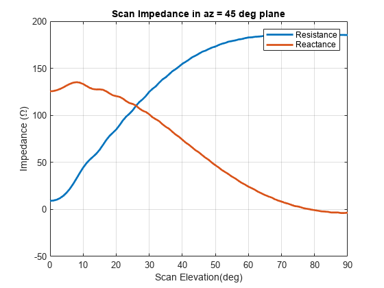
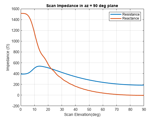
Section below shows the analysis result with higher number of terms in the scan impedance in 3 planes, azimuth = 0, 45 and 90 deg respectively. It takes about 100 seconds per scan plane on a 2.4 GHz machine with 32 GB memory.
az = [0 45 90];            % E,D,H-plane
load scanZData
E-plane
figure
plot(el,real(scanZ50terms(1,:)),el,imag(scanZ50terms(1,:)),LineWidth=2);
grid on
legend("Resistance","Reactance")
xlabel("Scan Elevation(deg)")
ylabel("Impedance (\Omega)")
title(["Scan Impedance in az = " num2str(az(1)) " deg plane"])

D-plane
figure
plot(el,real(scanZ50terms(2,:)),el,imag(scanZ50terms(2,:)),LineWidth=2);
grid on
legend("Resistance","Reactance")
xlabel("Scan Elevation(deg)")
ylabel("Impedance (\Omega)")
title(["Scan Impedance in az = " num2str(az(2)) " deg plane"])

H-plane
figure
plot(el,real(scanZ50terms(3,:)),el,imag(scanZ50terms(3,:)),LineWidth=2);
grid on
legend("Resistance","Reactance")
xlabel("Scan Elevation(deg)")
ylabel("Impedance (\Omega)")
title(["Scan Impedance in az = " num2str(az(3)) " deg plane"])

Infinite Array Impedance Variation with Frequency
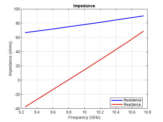
Fix the scan angle to a specific value and sweep the frequency to observe the impedance behavior of this unit cell element.
az_scan = 0;
el_scan = 45;
percent_bw = 0.15;
bw = percent_bw*freq;
fmin = freq - bw/2;
fmax = freq + bw/2;
infArray.ScanAzimuth = az_scan;
infArray.ScanElevation = el_scan;
figure
impedance(infArray,linspace(fmin,fmax,51));

Calculate Isolated Element Pattern and Impedance
Use the scan impedance data from the infinite array analysis to derive the scan element pattern (also known as embedded/array element pattern in case of finite arrays). As indicated in [1]-[4] use the isolated element pattern and impedance to calculate it. Do this by analyzing the dipole backed by an infinite reflector and calculating its power pattern and impedance at 10 GHz.
r.GroundPlaneLength = inf;
r.GroundPlaneWidth = inf;
giso = nan(numel(az),numel(el));
gisodB = nan(numel(az),numel(el));
for i = 1:numel(az)
    giso(i,:) = pattern(r,freq,az(i),el,Type="power");
    gisodB(i,:) = 10*log10(giso(i,:));
    gisodB(i,:) = gisodB(i,:) - max(gisodB(i,:));
end
Ziso = impedance(r,freq);
Calculate and Plot Scan Element Pattern
Define the generator impedance to calculate the scan element pattern. This example uses broadside scan resistance as the generator impedance.
Rg = 185;
Xg = 0;
Zg = Rg + 1i*Xg;
gs = nan(numel(az),numel(el));
gsdB = nan(numel(az),numel(el));
for i = 1:numel(az)
    gs(i,:) = 4*Rg*real(Ziso).*giso(i,:)./(abs(scanZ50terms(i,:) + Zg)).^2;
    gsdB(i,:)= 10*log10(gs(i,:));
    gsdB(i,:)= gsdB(i,:) - max(gsdB(i,:));
end

figure
plot(el,gsdB(1,:),el,gsdB(2,:),el,gsdB(3,:),LineWidth=2.0)
grid on
axis([0 90 -20 0])
xlabel("Scan Elevation (deg.)")
ylabel("Power pattern(dB)")
title(strcat("E-Plane (az = 0 deg.) Power Pattern"))
legend("az = 0 deg","az = 45 deg","az = 90 deg",Location="best")

Reference
[1] J. Allen, "Gain and impedance variation in scanned dipole arrays," IRE Transactions on Antennas and Propagation, vol.10, no.5, pp.566-572, September 1962.
[2] R. C. Hansen, Phased Array Antennas, Chapter 7 and 8, John Wiley & Sons Inc.,2nd Edition, 1998.
[3] R. J. Mailloux, 'Phased Array Antenna Handbook', Artech House,2nd edition, 2005
[4] W. Stutzman, G. Thiele, 'Antenna Theory and Design', John Wiley & Sons Inc., 3rd Edition, 2013.
See Also
Modeling Infinite Ground Plane in Antennas and Arrays | Infinite Array of Microstrip Patch Antenna on Teflon Substrate