Infinite Arrays
What Are Infinite Arrays?
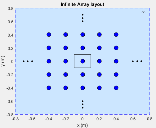
Infinite arrays are rectangular arrays of infinite extent. In an infinite array, a single element called a unit cell, is repeated uniformly an infinite number of times along a plane.
Infinite Array Analysis
All arrays used in real-world scenarios are finite. But antenna arrays used in radio astronomy, air defense, or surveillance radar can have more than 1000 antenna elements. In such large arrays, the electromagnetic analysis of each element is tedious and time consuming.
Infinite array analysis ignores the effect of truncation (edge effect) at array edges. The method analyzes the behavior of the active antenna element as a function of frequency and scan. The goal of infinite array analysis is to extract the behavior of the active antenna element embedded in the array.
Assumptions
For infinite array analysis, array size must be greater than
10-by-10. The technique makes other assumptions:
Each element is identical.
Each element is uniformly excited in amplitude.
All elements are spaced uniformly in two dimensions.
Infinite Array Solver
To model an infinite array, the method of moments (MoM) formulation is changed to account for the infinite behavior by replacing Green's functions with periodic Green's functions. The periodic Green's function is an infinite double summation.
| Green's Function | Periodic Green’s Function |
|---|---|
|
|
|
dx and dy are the ground plane dimensions that define the x and y dimensions of the unit cell. θ and Φ are the scan angles.
The periodic Green's function has an additional exponential term added to the infinite sum. The Φmn term accounts for the scanning of the infinite array. The periodic Green's function also accounts for the effect of mutual coupling.
Create Infinite Array Using Antenna Toolbox
To create an infinite array, use the infiniteArray object to repeat a single antenna element (unit cell), infinitely
along the X-Y plane. The layout function displays a typical unit
cell.
infarray = infiniteArray;
layout(infarray)
Choose a Unit Cell
You can use any antenna from the Antenna Toolbox™ as the unit cell. The unit cell requires a ground plane to specify the boundaries. You can use a reflector to back antennas that do not have a ground plane.
The default reflector properties are:
r = reflector
 reflector with properties:

              Exciter: [1x1 dipole]
    GroundPlaneLength: 0.2000
     GroundPlaneWidth: 0.2000
              Spacing: 0.0750
                 Tilt: 0
             TiltAxis: [1 0 0]
The default unit cell in an infinite array is a reflector that has a dipole as an
exciter. The Spacing property gives the distance between the reflector
and the exciter. The default infinite array properties are:
infarray = infiniteArray
 infiniteArray with properties:

          Element: [1x1 reflector]
      ScanAzimuth: 0
    ScanElevation: 90
show (infarray)

The dotted blue box bounds the unit cell. Ground plane length and ground plane width of the unit cell are the dimensions of the antenna element of the infinite array.
An antenna with a ground plane, such as a microstrip patch antenna, is specified
directly as an Element of an infinite array.
infarray = infiniteArray(Element=patchMicrostrip)
infarray =
  infiniteArray with properties:

          Element: [1x1 patchMicrostrip]
      ScanAzimuth: 0
    ScanElevation: 90
show(infarray)
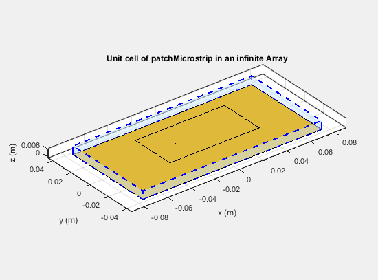
The Antenna Toolbox infinite array is located in the X-Y plane. Unit cells consisting of antennas
with ground planes are also located in the X-Y plane. For antennas used as unit cells, such
as the one in this example, you ignore the value of the Tilt
property.
Scan Infinite Arrays
You scan a finite array by specifying the appropriate phase shift for each antenna element. In Antenna Toolbox, you specify the scan angle (in azimuth and elevation) and frequency for infinite array analysis. By default, an array always scans at boresight (azimuth = 0 degrees and elevation = 90 degrees).
infarray = infiniteArray
 infiniteArray with properties:

          Element: [1x1 reflector]
      ScanAzimuth: 0
    ScanElevation: 90
To change the scan angles, change the values of ScanAzimuth and
ScanElevation.
Scan Impedance and Scan Element Pattern
To calculate the scan impedance for an infinite array, use the impedance function as a function of scan angle. Fixing the scan angle pair and
sweeping the frequency variable reveals the frequency dependency in the scan impedance.
Because ScanAzimuth and ScanElevation are scalar
values, you must use a for-loop to calculate the complete scan impedance
of the array. For more information on calculating the scan impedance and the scan element
pattern see, Infinite Array Analysis.
Scan Element Pattern
To calculate the scan element pattern using scan impedance, use these expressions:
Rg — Resistance of generator
Zg — Impedance of generator
Zs — Scan impedance
giso(θ) — Pattern of isolated element
Riso— Resistance of isolated element
The scan element pattern can also be expressed in terms of the reflection coefficient, Γ(θ):
The Antenna Toolbox software calculates the scan element pattern of a finite array by driving just a single element. You terminate all the other elements using a suitable impedance. The resulting element pattern includes mutual coupling and is valid for all scan angles.
Compare Scan Element Pattern of Finite and Infinite Arrays
Case 1: Compare finite array and infinite array with unit cell of dimensions 0.5λ × 0.5λ
To calculate the scan element pattern of the finite arrays, first, create a
reflector-backed dipole. Set the dipole dimensions to and and the ground plane dimensions to 0.5λ × 0.5λ. Place the dipole at a distance of h = λ/4 from the reflector. The ground plane dimensions set the boundaries of
the unit cell. Create finite arrays of sizes 11-by-11,
15-by-15, and 17-by-17 using this unit cell.
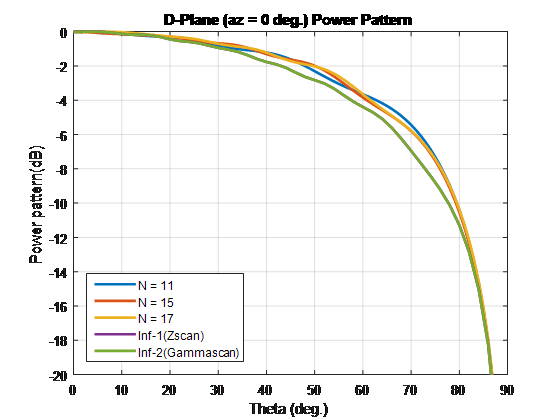
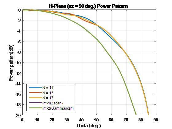
For finite arrays, calculate the scan element pattern by driving a single element in the array. Terminate all other finite array elements using the broadside resistance of the infinite array. For an infinite array with the unit cell of dimensions 0.5λ × 0.5λ, the broadside resistance is 176 Ω. Calculate the scan element pattern for E-, D-, and H-planes of all three finite arrays.
To calculate the scan element pattern of an infinite array, create an infinite array
using the same unit cell and the infiniteArray class. Calculate the scan
impedance for three scan planes: E, D, and H. Compute the pattern of the isolated element
(dipole backed by reflector). Finally, use the equations from the previous section to
generate the scan element pattern for the infinite array.
Perform all analysis at 10 GHz. To compare the patterns of finite and infinite array, overlay them on the same plot.

Case 2: Compare finite array and infinite array with unit cell of dimensions 0.7λ × 0.7λ
To compare the scan element pattern of these array types and infinite arrays, repeat the process in case 1. Using these unit cell dimensions creates grating lobes. Terminate the finite arrays using 86-Ω resistance. For an infinite array with unit cell of dimensions 0.7λ × 0.7λ, the broadside resistance is 86 Ω.
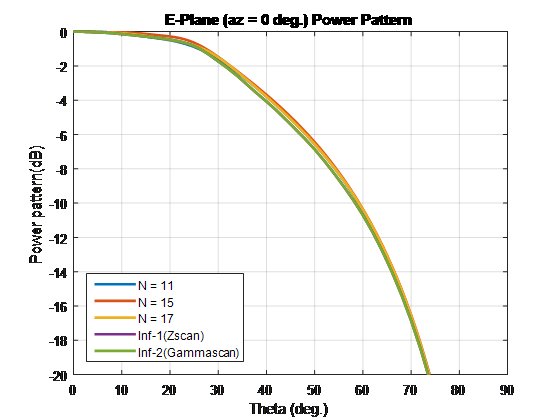

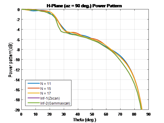
For finite arrays of size greater than 10 x 10, the scan element patterns in the E-, D-, and H-planes match the patterns of the infinite array scan element.
Impact of Infinite Double Summation
As show in the Green’s equations, the periodic Green's function has an infinite double summation in (m, n). When performing infinite array analysis, the number of terms in the double summation affects the accuracy of the final solution. Higher number of terms results in better accuracy but increases computation time.
By default, Antenna Toolbox uses 10 terms for each summation term
(m, n) to perform infinite array analysis. The total
summation term length is 2*10+1 (-10 to +10). To modify the number
of terms, use the method numSummationTerms.
Higher number of terms are required if:
You observe negative values for scan resistance for certain scan angles at certain frequencies.
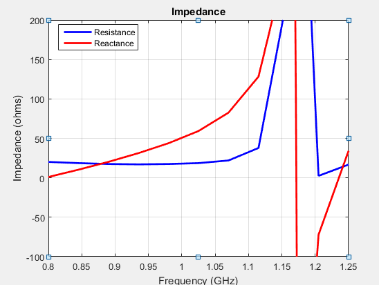
You must investigate for convergence when scan impedance shows slow variations.

References
[1] Mailloux, R. J. Phased Array Antenna Handbook. Norwood, MA: Artech House. 2nd Edition. 2005.
[2] Hansen, R. C. Phased Array Antennas. Hoboken, NJ: John Wiley & Sons Inc. 2nd Edition. 1998, pp. 221–313.
[3] Allen, J. "Gain and impedance variation in scanned dipole arrays." IRE Transactions on Antennas and Propagation. Vol. 10, Number 5, September 1962, pp. 566–572.
[4] Wasylkiwskyj, W., and W. Kahn. "Efficiency as a measure of size of a phased-array antenna." IEEE Transactions on Antennas and Propagation. Vol. 21, Number 6, November 1973, pp. 879–884.
[5] Holter, H., and H. Steyskal. "On the size requirement for finite phased-array models." IEEE Transactions on Antennas and Propagation. Vol. 50, Number 6, June 2002, pp. 836–840.