Maximizing Gain and Improving Impedance Bandwidth of E-Patch Antenna
This example shows how to optimize an E-patch antenna in the Antenna Designer app using the SADEA optimizer.
Antenna Selection
Enter antennaDesigner at the MATLAB® command prompt to open the app.
In the blank canvas, click NEW.
From the ANTENNA GALLERY dropdown, under PATCH FAMILY, select an E-patch antenna.
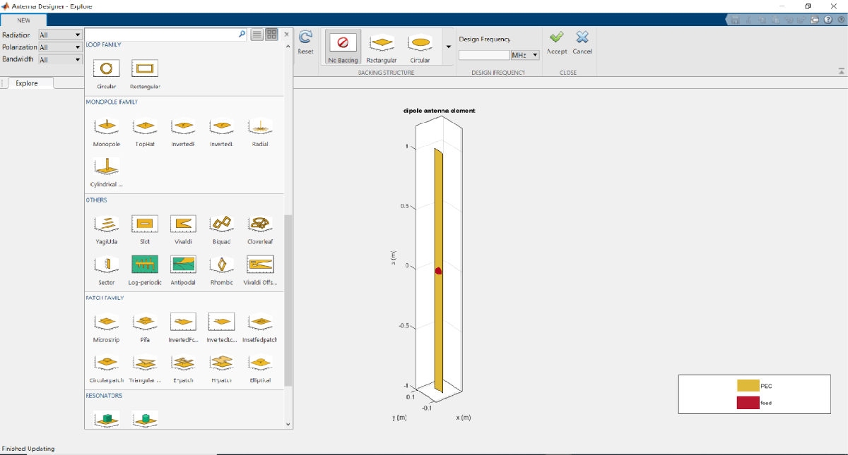
Set the design frequency to 6.6 GHz. To analyze the antenna, click Accept.
Analyze 3D Radiation Pattern
Click on 3D Pattern. Observe the radiation pattern and the maximum gain.
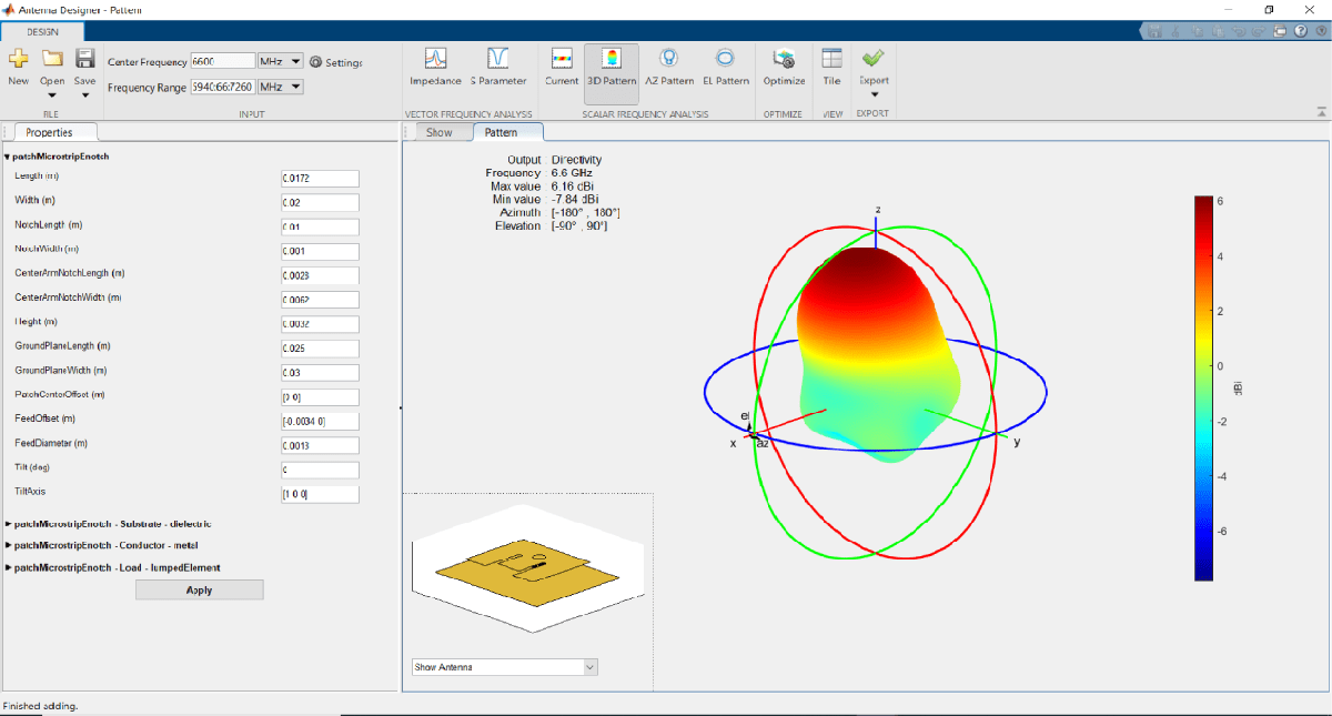
The maximum gain of the antenna is 6.16 dBi as shown on the top left side of the pattern figure.
Analyze
Click S Parameter.
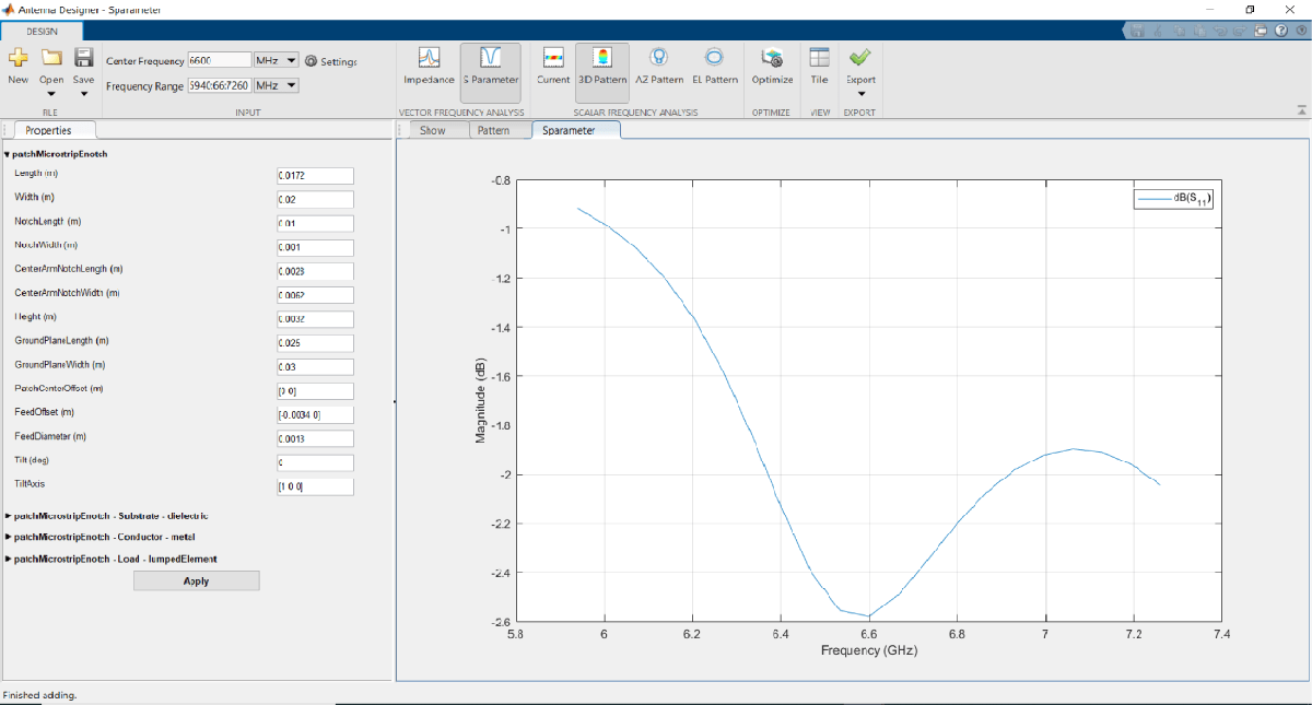
Observe that the of the antenna does not show any impedance bandwidth within the frequency range and the current E-patch antenna design might not be an optimized one. To improve the gain and the impedance bandwidth, optimize the antenna using the optimizer tab.
Setup Optimization Problem
Any optimization problem typically requires following inputs.
Objective function: Main goal of the optimization. It evaluates the analysis function and minimizes or maximizes the output of the function. In this example, maximizing the gain of the antenna is the objective function.
Design variables: The input variables to the objective function. These variables are changed by the optimizer within a pre-set range of values called as the bounds of the variables. In this example, the dimensions of the E-patch are the design variables.
Constraint functions (if necessary): Functions which restrict a desired analysis function value on the antenna. In this example, the constraint function is S11 less than -10 db to obtain an impedance bandwidth.
Other inputs: Other inputs may include the number of iterations, the input center frequency, and the input frequency, the number of iterations, the frequency at which the analysis is performed, etc.
Optimization Function
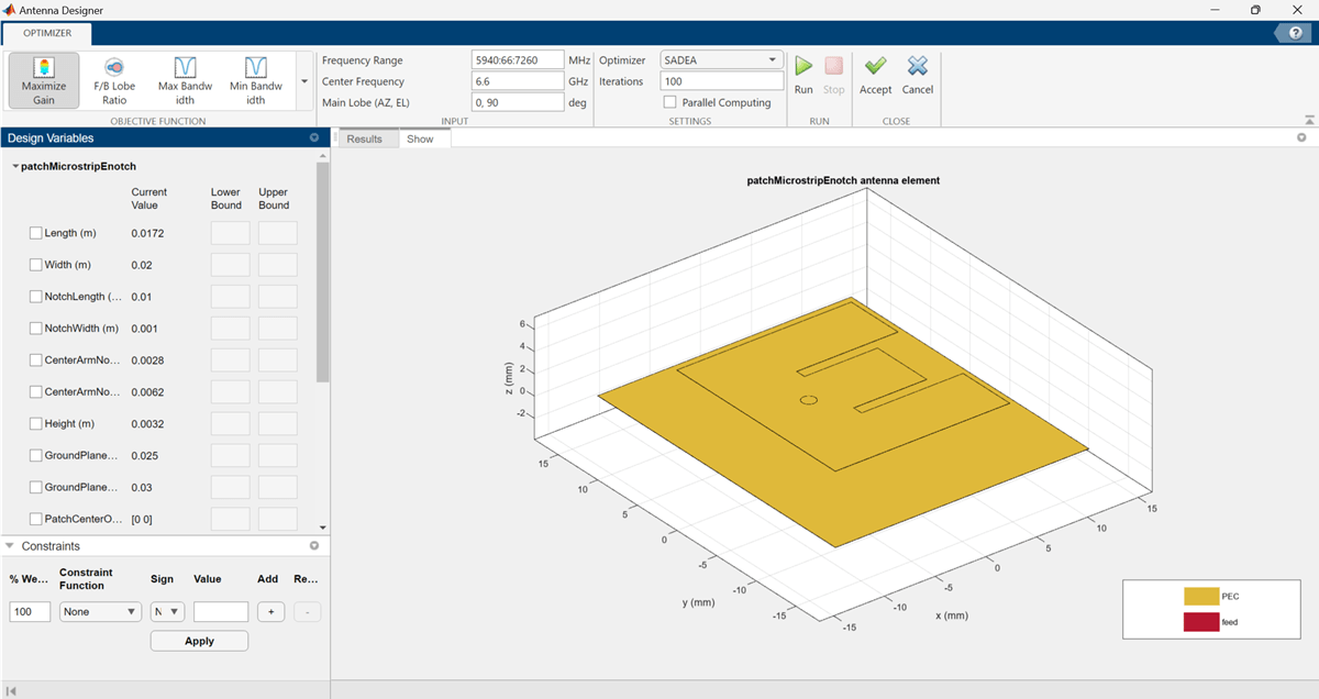
To optimize the E-patch, click on the Optimize button.
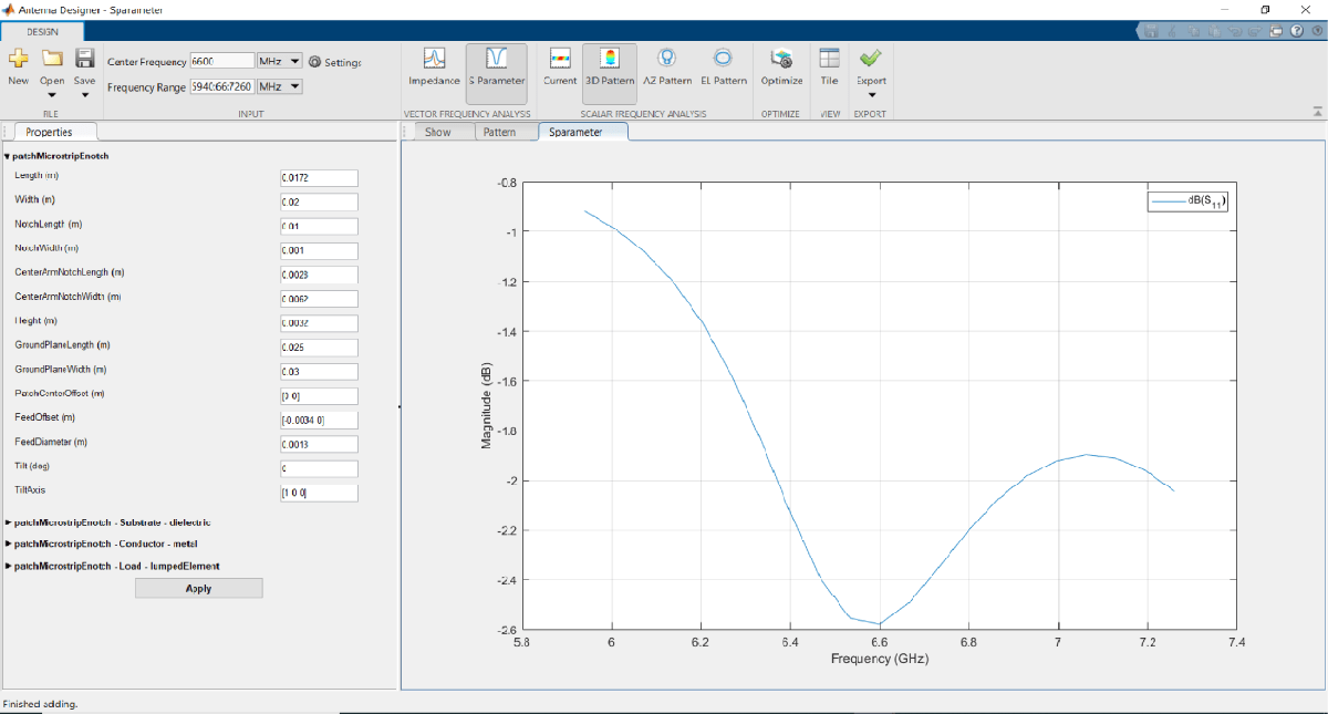
To select an objective function, use the OBJECTIVE FUNCTION Gallery drop down. Since the goal is to maximize the gain of the antenna, click on Maximize Gain.
Design Variables and Constraints
To set up the design variables, click on the Design Variables tab. Click on the checkboxes present on the left-hand side of the properties to choose the required design variables. The optimizer would change these chosen properties to obtain a maximum gain for the antenna.
Enter bounds for the design variables as follows:

Click Apply to set the variables.
To set up the constraints, click on the Constraints tab.
Select S11 (dB) from the Constraint Function. Select < operator from sign and enter value as -10.
Click Apply.
In the SETTINGS section, enter Iterations as 300 to give the number of iterations to run for the optimizer. Click Parallel Computing in Settings section if you have Parallel Computing Toolbox™ license and want to use it for the optimization. To start the start optimization, click the Run button.

Optimization
The SADEA is a surrogate model-based optimization which contains two stages
Building model
Optimizing
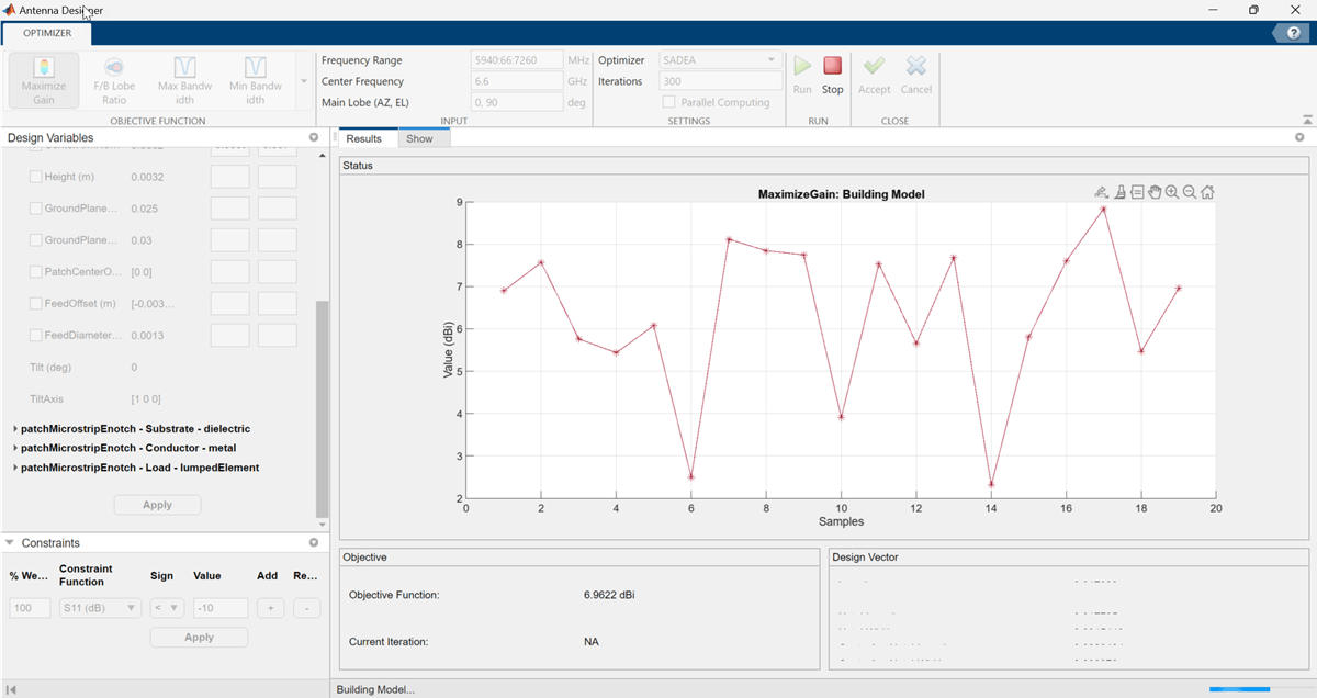
Building Model:
In the model building stage, the optimizer makes a surrogate model from the design space, and the specified objective and the constraints function. It diversely goes through the design space and performs analysis on these sample points.
So, the x-axis shows the number of samples and the y-axis shows the value of the analysis function value at that sample. The bottom left side show the current sample value and the bottom right side shows the design variables. The optimizer within decides and takes appropriate number of samples to build the model. After the model is built, the optimizer starts running iterations.
Optimizing
In the optimizing stage, the x-axis shows the number of iterations and the y-axis shows the objective function values. From the plots shown on the optimizing stage, you can understand the trend of convergence.
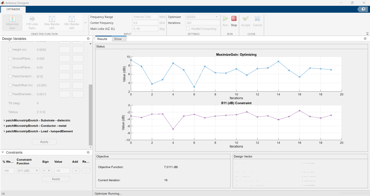
Notice that, the objective as well as the constraint plots show fewer deviations from after the 150th iteration. This indicates that the objective is converging.

Optimized 3D Pattern and Bandwidth
Once the optimization is complete, click on Accept. This takes you back to the previous page.
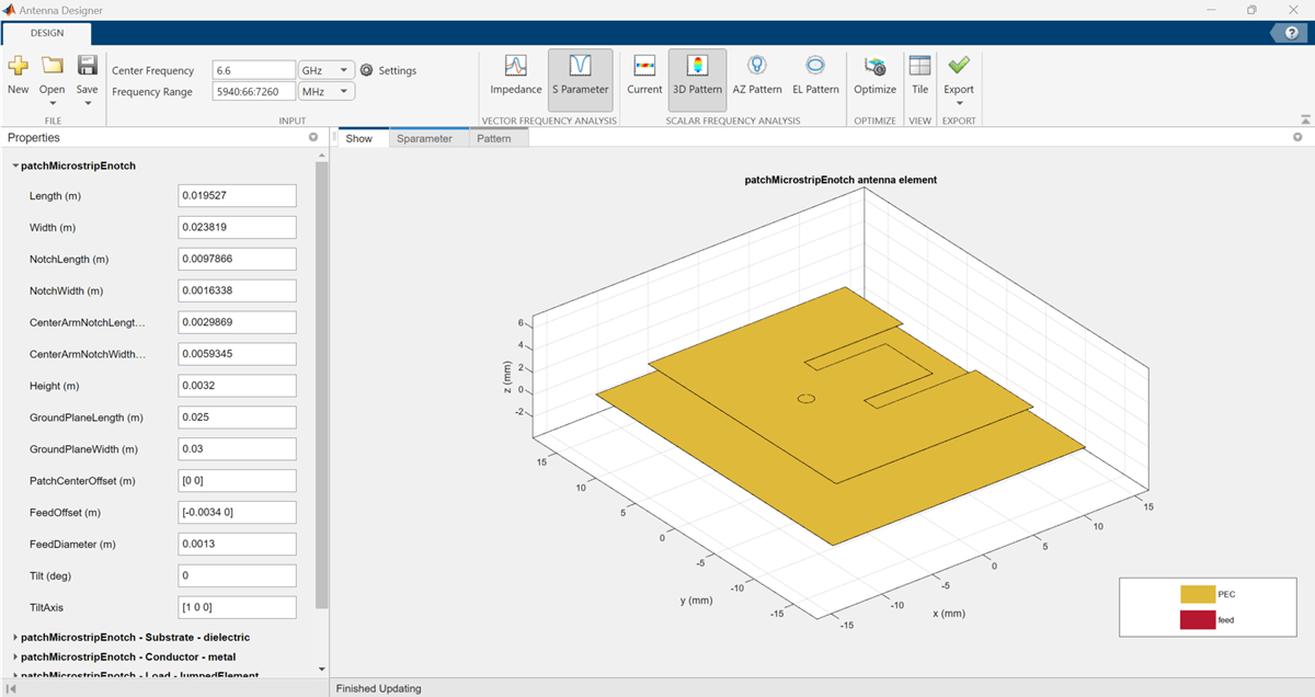
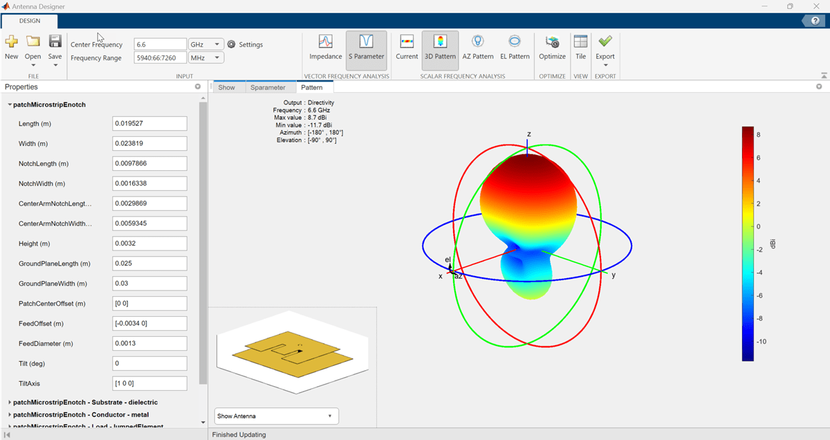
Click on Pattern to observe the 3D radiation pattern of the optimized antenna. Now, the maximum directivity is 8.7 dBi.
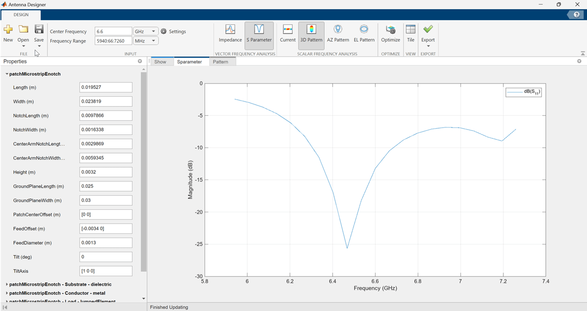
Click on S Parameter to observe the impedance bandwidth of the antenna. The optimized antenna shows a bandwidth of around 6.25 GHz to 6.669 GHz.

See Also
Surrogate Based Optimization of Six-Element Yagi-Uda Antenna