Method of Moments Solver for Metal Structures
Method of Moments computation technique for metal antennas.
The first step in the computational solution of electromagnetic problems is to discretize Maxwell's equations. The process results in this matrix-vector system:
V — Applied voltage vector. This signal can be voltage or power applied to the antenna or an incident signal falling on the antenna.
I — Current vector that represents current on the antenna surface.
Z — Interaction matrix or impedance matrix that relates V to I.
Antenna Toolbox™ uses method of moments (MoM) to calculate the interaction matrix and solve system equations.
MoM Formulation
The MoM formulation is split into three parts.
Discretization of Metals
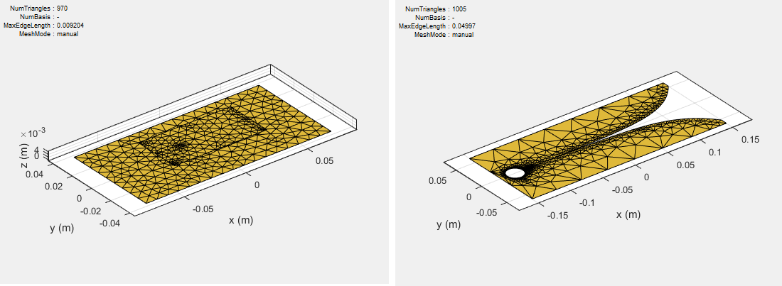
Discretization enables the formulation from the continuous domain to the discrete domain. This step is called meshing in antenna literature. In the MoM formulation, the metal surface of the antenna is meshed into triangles.
Basis Functions
To calculate the surface currents on the antenna structure, you first define basis functions. Antenna Toolbox uses Rao-Wilton-Glisson (RWG) [2] basis functions. The arrows show the direction of current flow.
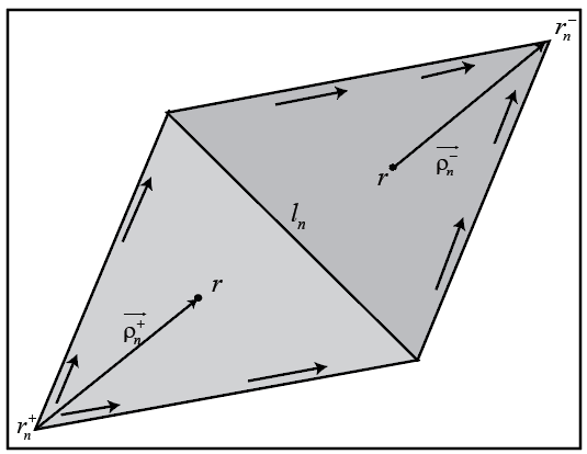
The basis function includes a pair of adjacent (not necessarily coplanar) triangles and resembles a small spatial dipole with linear current distribution. Each triangle is associated with a positive or negative charge.
For any two triangle patches, and , having areas and , and sharing common edge , the basis function is
— Vector drawn from the free vertex of triangle to observation point
— Vector drawn from the observation point to the free vertex of the triangle
and
The basis function is zero outside the two adjacent triangles and . The RWG vector basis function is linear and has no flux (no normal component) through its boundary.
Interaction Matrix
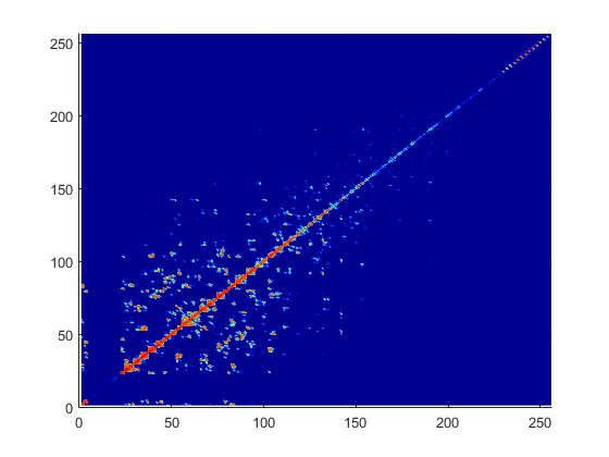
The interaction matrix is a complex dense symmetric matrix. It is a square N-by-N matrix, where N is the number of basis functions, that is, the number of interior edges in the structure. A typical interaction matrix for a structure with 256 basis functions is shown:
To fill out the interaction matrix, calculate the free-space Green's function between all basis functions on the antenna surface. The final interaction matrix equations are:
where
— Free-space Green's function
To calculate the interaction matrix, excite the antenna by a voltage of 1 V at the feeding edge. So the voltage vector has zero values everywhere except at the feeding edge. Solve the system of equations to calculate the unknown currents. Once you determine the unknown currents, you can calculate the field and surface properties of the antenna.
Neighbor Region
From the interaction matrix plot, you observe that the matrix is diagonally dominant. As you move further away from the diagonal, the magnitude of the terms decreases. This behavior is same as the Green's function behavior. The Green's function decreases as the distance between r and r' increases. Therefore, it is important to calculate the region on the diagonal and close to the diagonal accurately.
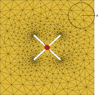
This region on and around the diagonal is called neighbor region. The neighbor region is defined within a sphere of radius R, where R is in terms of triangle size. The size of a triangle is the maximum distance from the center of the triangle to any of its vertices. By default, R is twice the size of the triangle. For better accuracy, a higher-order integration scheme is used to calculate the integrals.
Singularity Extraction
Along the diagonal, r and r' are equal and defines Green's function becomes singular. To remove the singularity, extraction is performed on these terms.
The two integrals on the right side of the equations, called potential or static integrals are found using analytical results [3].
Finite Arrays
The MoM formulation for finite arrays is the same as for a single antenna element. The main difference is the number of excitations (feeds). For finite arrays, the voltage vector is now a voltage matrix. The number of columns are equal to the number of elements in the array.
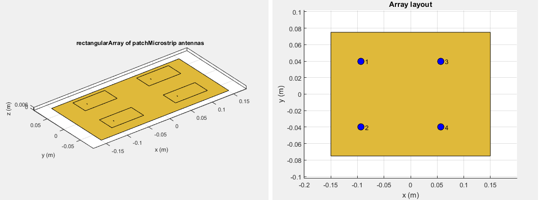
For example, the voltage vector matrix for a 2-by-2
array of rectangular patch antenna has four columns as each antenna can be excited
separately.
Infinite Array
To model an infinite array, you change the MoM to account for the infinite behavior. To do so, you replace the free-space Green's functions with periodic Green's functions. The periodic Green's function is an infinite double summation.
| Green's Function | Periodic Green's Function |
|---|---|
|
|
|
dx and dy are the ground plane dimensions that define the x and y dimensions of the unit cell. θ and Φ are the scan angles.
Comparing the two Green's functions, you observe an additional exponential term that is added to the infinite sum. The Φmn accounts for the scanning of the infinite array. The periodic Green's function also accounts for the effect of mutual coupling.
For more information see, Infinite Arrays.
References
[1] Harringhton, R. F. Field Computation by Moment Methods. New York: Macmillan, 1968.
[2] Rao, S. M., D. R. Wilton, and A. W. Glisson. “Electromagnetic scattering by surfaces of arbitrary shape.” IEEE. Trans. Antennas and Propagation, Vol. AP-30, No. 3, May 1982, pp. 409–418.
[3] Wilton, D. R., S. M. Rao, A. W. Glisson, D. H. Schaubert, O. M. Al-Bundak. and C. M. Butler. “Potential Integrals for uniform and linear source distribution on polygonal and polyhedral domains.” IEEE. Trans. Antennas and Propagation. Vol. AP-30, No. 3, May 1984, pp. 276–281.
[4] Balanis, C.A. Antenna Theory. Analysis and Design. 3rd Ed. New York: John Wiley & Sons, 2005.
See Also
Finite Conductivity and Thickness Effect in MoM Solver | Infinite Arrays