Graphic EQ
Standards-based graphic equalizer
Libraries:
Audio Toolbox /
Filters
Description
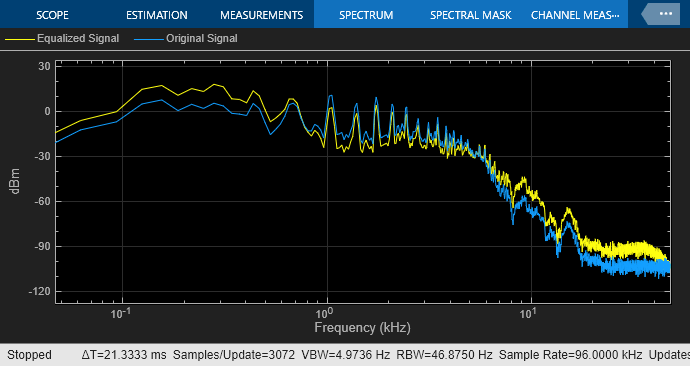
The Graphic EQ block implements a graphic equalizer that can tune the gain on individual octave or fractional octave bands. The block filters the data independently across each input channel over time using the filter specifications. Center frequencies for bands in the graphic equalizer are based on the ANSI S1.11-2004 standard.
Examples
Perform Graphic Equalization
Examine the Graphic EQ block in a Simulink® model and tune parameters.
Ports
Input
Port_1 — Input signal
matrix | 1-D vector
Matrix input –– Each column of the input is treated as an independent channel.
1-D vector input –– The input is treated as a signal channel.
Data Types: single
| double
Output
Port_1 — Output signal
matrix
The Graphic EQ block outputs a signal with the same data type as the input signal. The size of the output depends on the size of the input:
Matrix input –– The block outputs a matrix the same size and data type as the input signal.
1-D vector input –– The block outputs an N-by-1 matrix (column vector), where N is the number of elements in the 1-D vector input.
Data Types: single
| double
Parameters
If a parameter is listed as tunable, then you can change its value during simulation.
EQ Order — Order of individual equalizer bands
2
(default) | positive even integer
Specify the order of individual equalizer bands as a positive even integer. All equalizer bands have the same order.
Tunable: Yes
Bandwidth — Filter bandwidth (octaves)
1 octave
(default) | 2/3 octave
| 1/3 octave
Specify the filter bandwidth as 1 octave
,
2/3 octave
, or 1/3
octave
.
The ANSI S1.11-2004 standard defines the center and edge frequencies of your equalizer. The ISO 266:1997(E) standard specifies corresponding preferred frequencies for labeling purposes.
1-Octave Bandwidth
Center frequencies | 32 63 126 251 501 1000 1995 3981 7943
15849 |
Edge frequencies | 22 45 89 178 355 708 1413 2818 5623 1122
22387 |
Preferred frequencies | 31.5 63 125 250 500 1000 2000 4000 8000
16000 |
2/3-Octave Bandwidth
Center frequencies | 25 40 63 100 158 251 398 631 1000 1585 2512
3981 6310 10000 15849 |
Edge frequencies | 20 32 50 79 126 200 316 501 794 1259 1995
3162 5012 7943 12589 19953 |
Preferred frequencies | 25 40 63 100 160 250 400 630 1000 1600 2500
4000 6300 10000 16000 |
1/3-Octave Bandwidth
Center frequencies | 25 32 40 50 63 79 100 126 158 200 251 316
398 501 631 794 1000 1259 1585 1995 2512 3162 3981
5012 6310 7943 10000 12589 15849
19953 |
Edge frequencies | 22 28 35 45 56 71 89 112 141 178 224 282 355
447 562 708 891 1122 1413 1778 2239 2818 3548 4467
5623 7079 8913 11220 14125 17783
22387 |
Preferred frequencies | 25 31.5 40 50 63 80 100 125 160 200 250 315
400 500 630 800 1000 1250 1600 2000 2500 3150 4000
5000 6300 8000 10000 12500 16000
20000 |
Tunable: No
Structure — Type of implementation
Cascade
(default) | Parallel
Specify the type of implementation as Cascade
or Parallel
. See Algorithms and
Graphic Equalization for information about these
implementation structures.
Tunable: No
Gains — Gain of each octave or fractional octave band (dB)
0
| scalar
Specify the gain of each octave or fractional octave band in dB. The number and position of filters in the graphic equalizer depends on the Bandwidth parameter.
Tunable: Yes
Variable name — Variable name of exported filter
myFilt
(default) | valid variable name
Name of the variable in the base workspace to contain the filter when it is exported. The name must be a valid MATLAB® variable name.
Overwrite variable if it already exists — Overwrite variable if it already exists
on
(default) | off
When you select this parameter, exporting the filter overwrites the
variable specified by the Variable name parameter if it
already exists in the base workspace. If you do not select this parameter
and the specified variable already exists in the workspace, exporting the
filter creates a new variable with an underscore and a number appended to
the variable name. For example, if the variable name is
var
and it already exists, the exported variable will
be named var_1
.
Export filter to workspace — Export filter to workspace
button
Export the filter to the base workspace in the variable specified by the Variable name parameter.
Tips
You cannot export the filter if you have enabled the Inherit sample rate from input parameter and the model is not running.
Inherit sample rate from input — Specify source of input sample rate
off (default) | on
When you select this parameter, the block inherits its sample rate from the input signal. When you clear this parameter, specify the sample rate in Input sample rate (Hz).
Tunable: No
Input sample rate (Hz) — Sample rate of input
44100
(default) | scalar
Tunable: Yes
Dependencies
To enable this parameter, clear the Inherit sample rate from input parameter.
Simulate using — Specify type of simulation to run
Code generation
(default) | Interpreted execution
Interpreted execution
–– Simulate model using the MATLAB interpreter. This option shortens startup time and has simulation speed comparable toCode generation
. In this mode, you can debug the source code of the block.Code generation
–– Simulate model using generated C code. The first time you run a simulation, Simulink® generates C code for the block. The C code is reused for subsequent simulations, as long as the model does not change. This option requires additional startup time but the speed of the subsequent simulations is faster thanInterpreted execution
.
Tunable: No
Block Characteristics
Data Types |
|
Direct Feedthrough |
|
Multidimensional Signals |
|
Variable-Size Signals |
|
Zero-Crossing Detection |
|
Algorithms
The implementation of your graphic equalizer depends on the Structure parameter. See Graphic Equalization for a discussion of the pros and cons of the parallel and cascade implementations. Refer to the following sections to understand how these algorithms are implemented in Audio Toolbox™.
Parallel Structure
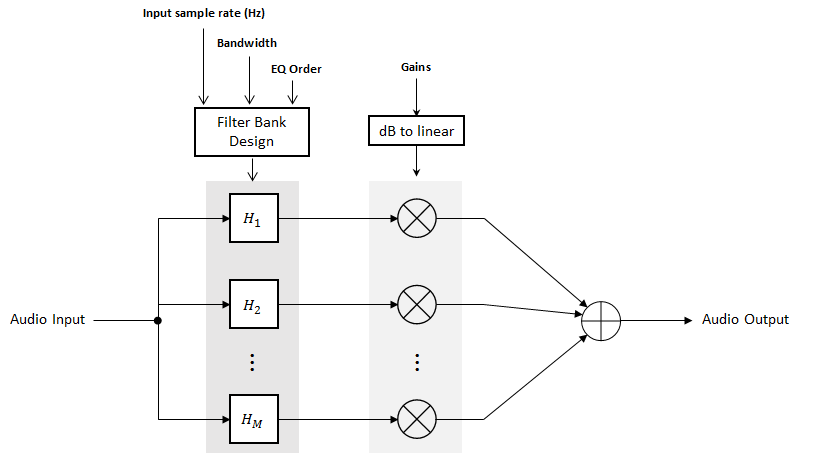
The parallel implementation designs the individual equalizers using the
octaveFilter
design method
and spaces them on the spectrum according to the ANSI
S1.11-2004 standard.
If you set the Input sample rate (Hz) parameter so that
the Nyquist frequency (Input sample rate
(Hz)/2
) is less than the final bandpass edge
defined by the ANSI S1.11-2004 standard, then:
The final bandpass filter is the one whose upper bandpass edge is less than the Nyquist frequency.
The final filter is implemented as a highpass filter designed by the
designParamEQ
function.
The input signal is fed into a filterbank of M filters, where M depends on the specified Bandwidth and Input sample rate (Hz) parameters.
Each branch of the filterbank is multiplied by the linear form of the corresponding element of the Gains parameter.
The branches are summed and the output signal is returned.
Cascade Structure
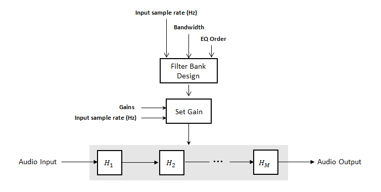
The cascade implementation designs the graphic equalizer filter bank using the
multibandParametricEQ
System object™.
If the EQ Order parameter is set to 2, then a gain correction is calculated according to [1]. The gain correction is independent of the requested gains. The gain correction is recomputed during the real-time processing only if the Input sample rate (Hz) parameter is modified.
If the EQ Order parameter is not set to 2, no gain
correction is applied and the requested gains are passed on to the
multibandParametricEQ
object.
The input signal is fed into a cascade of M biquad filters, where M depends on the specified Bandwidth and Input sample rate (Hz) parameters.
References
[1] Oliver, Richard J., and Jean-Marc Jot. "Efficient Multi-Band Digital Audio Graphic Equalizer with Accurate Frequency Response Control." Presented at the 139th Convention of the AES, New York, October 2015.
[2] Acoustical Society of America. American National Standard Specification for Octave-Band and Fractional-Octave-Band Analog and Digital Filters. ANSI S1.11-2004. Melville, NY: Acoustical Society of America, 2009.
[3] International Organization for Standardization. Acoustics –– Preferred frequencies. ISO 266:1997(E). Second Edition. 1997.
Extended Capabilities
C/C++ Code Generation
Generate C and C++ code using Simulink® Coder™.
Version History
Introduced in R2017b
MATLAB Command
You clicked a link that corresponds to this MATLAB command:
Run the command by entering it in the MATLAB Command Window. Web browsers do not support MATLAB commands.
Select a Web Site
Choose a web site to get translated content where available and see local events and offers. Based on your location, we recommend that you select: .
You can also select a web site from the following list
How to Get Best Site Performance
Select the China site (in Chinese or English) for best site performance. Other MathWorks country sites are not optimized for visits from your location.
Americas
- América Latina (Español)
- Canada (English)
- United States (English)
Europe
- Belgium (English)
- Denmark (English)
- Deutschland (Deutsch)
- España (Español)
- Finland (English)
- France (Français)
- Ireland (English)
- Italia (Italiano)
- Luxembourg (English)
- Netherlands (English)
- Norway (English)
- Österreich (Deutsch)
- Portugal (English)
- Sweden (English)
- Switzerland
- United Kingdom (English)
Asia Pacific
- Australia (English)
- India (English)
- New Zealand (English)
- 中国
- 日本Japanese (日本語)
- 한국Korean (한국어)