Surround Sound Matrix Encoding and Decoding
This example shows how to generate a stereo signal from a multichannel audio signal using matrix encoding, and how to recover the original channels from the stereo mix using matrix decoding. This example illustrates MATLAB® and Simulink® implementations. This example also shows how performance can be improved by using dataflow execution domain.
Introduction
Matrix decoding is an audio technique that decodes an audio signal with M channels into an audio signal with N channels (N > M) for play back on a system with N speakers. The original audio signal is usually generated using a matrix encoder, which transforms N-channel signals to M-channel signals.
Matrix encoding and decoding enables the same audio content to be played on different systems. For example, a surround sound multichannel signal may be encoded into a stereo signal. The stereo signal may be played back on a stereo system to accommodate settings where a surround sound receiver does not exist, or it may be decoded and played as surround if surround equipment is present [1].
In this example, we showcase a matrix encoder used to encode a four-channel signal (left, right, center and surround) to a stereo signal. The four original signals are then regenerated using a matrix decoder. This example is a simplified version of the encoding and decoding scheme used in the Dolby Pro Logic system [2].
Simulink Version
The audiomatrixdecoding model implements the audio matrix encoding/decoding example.

The input to the matrix encoder consists of four separate audio channels (center, left, right and surround).

Double-click the Audio Channels subsystem to launch a tuning dialog box. The dialog box enables you to control the relative power between the right channel and left channel inputs, as well as the power level of the surround channel.

You can also toggle between listening to any of the original, encoded or decoded audio channels by double-clicking the Audio Player Selector subsystem and selecting the channel of your choice from the dialog box drop down menu.
Matrix Encoder
The Matrix Encoder encodes the four input channels into a stereo signal.
Notice that since the input left and right channels only contribute to the output left and right channels, respectively, the output stereo signal conserves the balance between left and right channels.
The surround input channel is passed through a Hilbert transformer, thereby creating a 180 degree phase differential between the surround component feeding the left and right stereo outputs [2].
You may listen to the encoded left and right stereo signals by double-clicking the Audio Player Selector subsystem and selecting either the 'Encoded Total Left' or 'Encoded Total Right' channels.

Matrix Decoder
The Matrix Decoder extracts the four original channels from the encoded stereo signal.
The lowpass frequencies are first separated using a Linkwitz-Riley cross-over filter. For more information about the implementation of the Linkwitz-Riley filter, refer to Multiband Dynamic Range Compression.
The left and right stereo channels are passed through to the left and right output channels, respectively. Therefore, there is no loss of separation between left and right channels in the output.
The center output channel is equal to the sum of the stereo input signals, thereby canceling the phase-shifted surround left and right components.
The surround output channel is derived by first taking the difference of the stereo signals. Since the original input center signal contributes equally to both stereo channels, the center channel does not leak into the output surround signal. Moreover, note that the original left and right signals contribute to the output surround channel. The surround signal is delayed by 10 msec to achieve a precedence effect [3].
You may listen to the decoded surround signal by double-clicking the Audio Player Selector subsystem and selecting one of the decoded signals.

Improve Simulation Performance Using Dataflow Domain
This example can use dataflow execution domain in Simulink to make use of multiple cores on your desktop to improve simulation performance. To learn more about dataflow and how to run Simulink models using multiple threads, see Multicore Execution Using Dataflow Domain.
Specify Dataflow Execution Domain
In Simulink, you specify dataflow as the execution domain for a subsystem by setting the Domain parameter to Dataflow using Property Inspector. To access Property Inspector, in the Simulink Toolstrip, on the Modeling tab, in the Design gallery select Property Inspector or on the Simulation tab, Prepare gallery, select Property Inspector.

Dataflow domains automatically partition your model into multiple threads for better performance. Once you set the Domain parameter to Dataflow, you can use the Multicore tab analysis to analyze your model to get better performance. The Multicore tab is available in the toolstrip when there is a dataflow domain in the model. To learn more about the Multicore tab, see Perform Multicore Analysis for Dataflow.

Analyzing Concurrency in Dataflow Subsystem
For this example the Multicore tab mode is set to Simulation Profiling for simulation performance analysis.
It is recommended to optimize model settings for optimal simulation performance. To accept the proposed model settings, on the Multicore tab, click Optimize. Alternatively, you can use the drop menu below the Optimize button to change the settings individually.

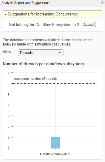
On the Multicore tab, click the Run Analysis button to start the analysis of the dataflow domain for simulation performance. Once the analysis is finished, the Analysis Report and Suggestions window shows how many threads the dataflow subsystem uses during simulation.
After analyzing the model, the Analysis Report and Suggestions window shows one thread because the data dependency between the blocks in the model prevents blocks from being executed concurrently. By pipelining the data dependent blocks, the dataflow subsystem can increase concurrency for higher data throughput. The Analysis Report and Suggestions window shows the recommended number of pipeline delays as Suggested for Increasing Concurrency. The suggested latency value is computed to give the best performance.
The following diagram shows the Analysis Report and Suggestions window where the suggested latency is 2 for the dataflow subsystem.

Click the Accept button to use the recommended latency for the dataflow subsystem. This value can also be entered directly in the Property Inspector for Latency parameter. Simulink shows the latency parameter value using  tags at the output ports of the dataflow subsystem.
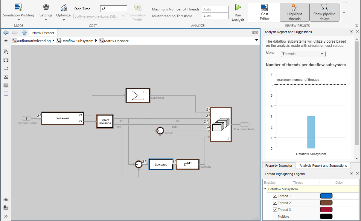
The Analysis Report and Suggestions window now shows the number of threads as 2 meaning that the blocks inside the dataflow subsystem simulate in parallel using 2 threads. Highlight threads highlights the blocks with colors based on their thread allocation as shown in the Thread Highlighting Legend. Show pipeline delays shows where pipelining delays were inserted within the dataflow subsystem using  tags.
tags.

Compensate for Latency
When latency is increased in the dataflow execution domain to break data dependencies between blocks and create concurrency, that delay needs to be accounted for in other parts of the model. For example, signals that are compared or combined with the signals at the output ports of the dataflow subsystem must be delayed to align in time with the signals at the output ports of the dataflow subsystem. In this example, the audio signal from the Audio Channels block that goes to the Audio Player Selector must be delayed to align with other signals going into the Audio Player Selector block. To compensate for the latency specified on the dataflow subsystem, use a delay block to delay this signal by two frames. For this signal, the frame length is 1024. A delay value of 2048 is set in the delay block to align the signal from the Audio Channels block and the signal processed through the dataflow subsystem.

Dataflow Simulation Performance
To measure performance improvement gained by using dataflow, compare execution time of the model with and without dataflow. The Audio Device Writer block runs in real time and limits the simulation speed of the model to real time. Comment out the Audio Device Writer block when measuring execution time. On a Windows desktop computer with Intel® Xeon® CPU W-2133 @ 3.6 GHz 6 Cores 12 Threads processor this model using dataflow domain executes 2.3x times faster compared to original model.
MATLAB Version
HelperAudioMatrixDecoderSim is the MATLAB function containing the audio matrix decoder example's implementation. It instantiates, initializes and steps through the objects forming the algorithm.
The function audioMatrixDecoderApp wraps around HelperAudioMatrixDecoderSim and iteratively calls it.
Execute audioMatrixDecoderApp to run the simulation. Note that the simulation runs until you explicitly stop it.
audioMatrixDecoderApp launches a UI designed to interact with the simulation. Similar to the Simulink version of the example, the UI allows you to tune the relative power between the right channel and left channel inputs, as well as the power level of the surround channel. You can also toggle between listening to any of the original, encoded or decoded audio channels by changing the value of the 'Audio Output' drop-down box in the UI.
There are also three buttons on the UI - the 'Reset' button will reset the simulation internal state to its initial condition and the 'Pause Simulation' button will hold the simulation until you press on it again. The simulation may be terminated by either closing the UI or by clicking on the 'Stop simulation' button.
MATLAB Coder™ can be used to generate C code for the function HelperAudioMatrixDecoderSim. In order to generate a MEX file for your platform, execute the command HelperMatrixDecodingCodeGeneration from a folder with write permissions.
By calling the wrapper function audioMatrixDecoderApp with 'true' as an argument, the generated MEX file can be used instead of HelperAudioMatrixDecoderSim for the simulation. In this scenario, the UI is still running inside the MATLAB environment, but the main processing algorithm is being performed by a MEX file. Performance is improved in this mode without compromising the ability to tune parameters.
References
[1] https://en.wikipedia.org/wiki/Matrix_decoder
[2] Dolby Pro Logic Surround Decoder: Principles of Operation, Roger Dressler, Dolby Labs