Servers Service Interface Properties
R2026bMap exported model functions to function prototype definitions in server service
Since R2026b
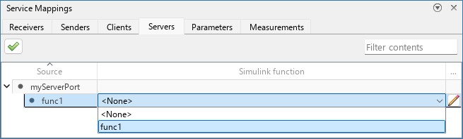
Use the Servers tab of the Service Mappings editor to map exported model functions to function prototype definitions of Server port blocks
Properties
The table entries in this tab are organized as parent entries with one-level collapsible child entries. Each parent entry corresponds to a Server port block and each child entry corresponds to a function prototype definition in the Server port block. To read about Server port blocks and function prototype definitions in them, see Configure Client-Server Communication Behavior.
This property is read-only.
Name of the model element that corresponds to the table entry.
Only applies to child entries. The name of the Simulink function mapped to the
function interface definition of the child entry, or None if
no model function is mapped to the function interface definition. From the list, select
the model function to map to the function interface definition of the child
entry.
The Simulink function and the function interface definition must have the same number of input arguments, and the same number of output arguments. Corresponding arguments must have identical identifiers. The name of the function in the Simulink Function block is not restricted to be identical to the name of the function in the Server port block prototype definition.
AUTOSAR
AUTOSAR
Use this property to combine events from a sender port with methods from a server port.
Only applies to parent entries.
By default, each Out Bus Element block maps to a separate AUTOSAR Adaptive Required port with the same name as the block. This includes both blocks that are mapped to sender services and blocks that are mapped to server services. To combine the events of a block that is mapped to sender services with the methods of a block that is mapped to server services onto a shared required port, specify the same required port as the Service port of both blocks. To learn about the AUTOSAR dictionary and required ports in it, see Define AUTOSAR Adaptive Software Component Ports and Interfaces.
To configure this property, click the pencil icon  at the end of the parent entry to open the dialog box. In the
AUTOSAR section, select the service port to use with this port.
at the end of the parent entry to open the dialog box. In the
AUTOSAR section, select the service port to use with this port.

Alternatively, you can select the parent port in the model canvas while the Property Inspector is open. Then, in the Service tab of the Property Inspector, in the AUTOSAR section, select the service port to use with this port.

More About
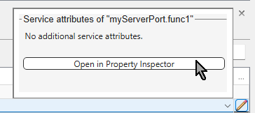
There are no additional properties to the server service interface, but you can still
open the dialog box by clicking the pencil icon . To use the dialog box for additional properties to open the
Property Inspector, click the Open in Property
Inspector button.
Version History
Introduced in R2026b

