Configure Simulink Functions and Function Callers with Client and Server Service Interface Definitions
R2026bClient and Server services correspond to platform-provided functions called by the code generated from the model implementing client and server port elements, respectively. Map each client port element to a Function Caller block and each server port element to a Simulink® Function block.
The client service act as a proxy of the Simulink function and the server service acts as a proxy of the function caller. This way, the function caller on the client side invokes the client port in the same manner it would invoke a Simulink function directly, and the Simulink function is invoked on the server side in the same manner it would be invoked by a function caller directly. The platform provides the communication layer, through which the proxies interact.
Before generating model code, map Simulink functions to server service interface definitions and map function callers to client service interface definitions. To see more about configuring client and server service interface definitions, see Configure Client-Server Communication Behavior.
Map Simulink Functions and Function Callers to Server and Client Service Interface Definitions
This example shows how to map Simulink® Function blocks to server service interface definitions and Function Caller blocks to client service interface definitions for code generation.
In the example you:
Update the client side model — you add a client port and a function caller block in the
ActuatorSWCmodel. Then, you map the function caller to the client port and you map the client port to client service interface definitions.Update server side model — you add a server port and a Simulink Function block in the
SpeedometerSWCmodel. Then, you map the Simulink function to the server port and you map the server port to server service interface definitions.Update the architecture system — you connect the new server port to the new client port.
Generate and explore code — see how the service interface definitions you configured are reflected in the model-generated code.
Open and Explore Architecture System
Open the architectural system SWArch.
soaArchSystem = "SWArch";
open_system(soaArchSystem)
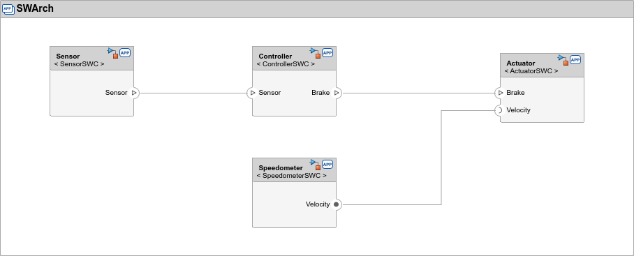
The server port, Velocity, in the model SpeedometerSWC is connected to the client port, Velocity, in the model ActuatorSWC.
Open and Explore Component Models
Open the component models ActuatorSWC and SpeedometerSWC as top models.
actuatorModel = "ActuatorSWC";
speedModel = "SpeedometerSWC";
open_system(actuatorModel)
open_system(speedModel)
In both models open the Service Mappings editor. In the actuator model, select the Clients tab and in the speedometer model, select the Servers tab.
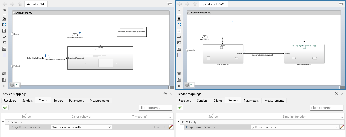
The actuator model is triggered by the brake command from the controller model. Once triggered, the actuator model performs a computation that involves calling the function getCurrentVelocity, which is defined in the speedometer model. The function caller is modeled as a Function Caller block in the actuator model and the function definition is modeled as a Simulink Function block in the speedometer model. The actuator model uses the function getCurrentVelocity in its calculations to determine whether to activate the brakes upon receiving a brake command from the controller model.
In the example you add another pair of function and caller, also modeled as a Simulink Function block in the speedometer model and a Function Caller block in the actuator model. The Function Caller block is mapped to a Client service function that acts as a proxy of the function to invoke, and the Simulink Function block is mapped to a Server service that acts as a proxy of the caller. The communication between the Client and Server services is managed by the platform. To allow successful invocation of the Simulink function by the remote function caller, they must match each other and because they communicate through the client and server services, their mapping to the services must match.
Update Client Side Model
In the model ActuatorSWC, you add a client port and a function caller block, and you map the function caller to the client port. These are the steps:
You add a Function Caller block and map it to the client port.
You map the client port to client service definitions, by configuring these client service properties:
Caller behavior — Determines how the client behaves after function invocation. Select Wait for server results to have the client block while waiting for server results, that are given as the return value of the function. Select Allow delayed server results to have the client continue execution without waiting, and attempt to poll the results from the server in every successive execution step.
Timeout — Specifies the maximum number of seconds the client waits for or attempt to poll server results. The value Inf indicates that timeout monitoring is disabled, so the caller waits or attempts polling for server results indefinitely. You can either manually enter Inf, or leave empty to have the software automatically treat the value as
Inf(and then the value Default:Inf is shown, but grayed out).
Add Client Port to Actuator Model
In the actuator model, add another Client port, on top of the existing, and name it Curvature:
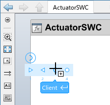
1) Click on the edge of the model canvas to open the floating menu. Then click the third item from the left to add a Client port.
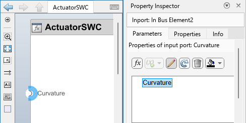
2) In the Property Inspector, on the Parameters tab, locate the newly added port and double-click its name to make it editable. Then, type Curvature and press Enter to rename the port.
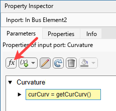
3) Click on the function button  to add a port element to the client port. The element is added with the default name. Click on it to revise it to
 curCurv = getCurCurv().
Add Function Caller Block and Map to Client Port
In the actuator model there is a Function-Caller Subsystem block. In it, there is a Function Caller block that is mapped to the client element function Velocity.getCurrentVelocity. Next to it, in the same function-caller subsystem, add another Function Caller block, name it curvFuncCaller, and map it to the new Client port element you previously created:
Double-click on the Function-Caller Subsystem block to open it.
Double-click on the canvas and add a Function Caller block above the existing Function Caller block.
Double-click the new Function Caller block to open its block parameters dialog box.
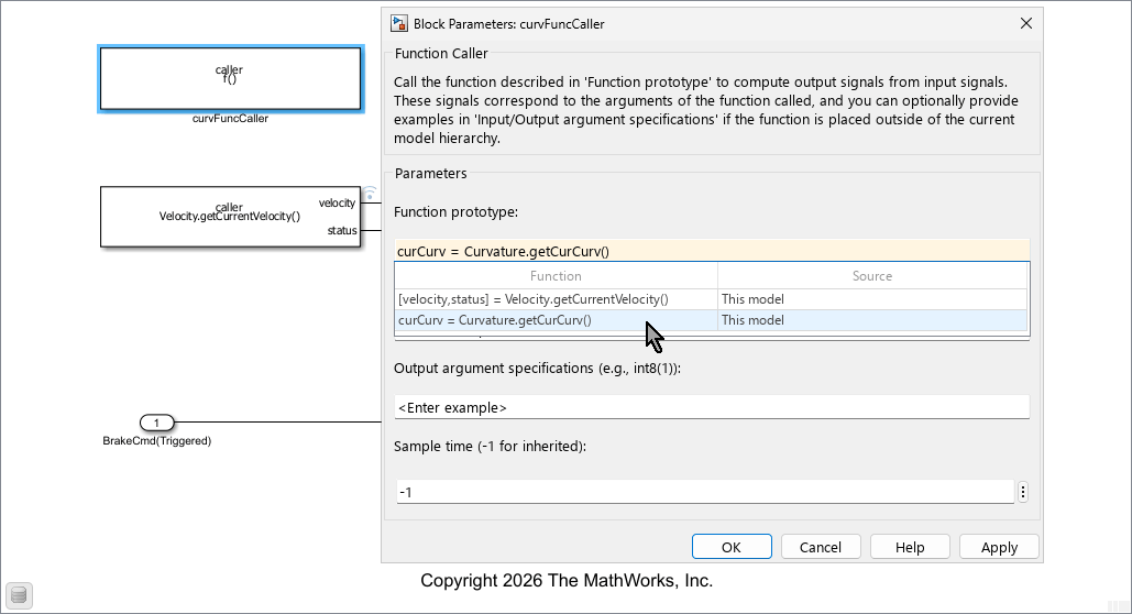
In the dialog box, select the value field of the parameter Function prototype, and press the arrow-down key to open the list of available client port elements to map this function caller to.
From the list, select the entry
curCurv = Curvature.getCurCurv().Click OK.
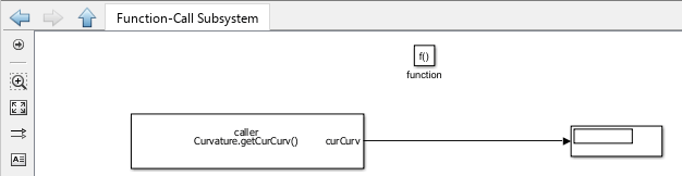
Connect a new Display block to the output port of the new function caller block, Curvature.getCurCurve.
Map Client Port to Client Service Interface Definitions
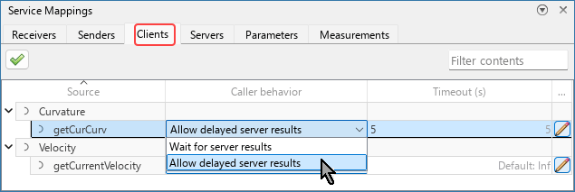
Open the Service Mappings editor and select the Clients tab. Locate the new client port entry, getCurCurv, under the parent entry, Curvature. Here you configure the client port with client service interface definitions by configuring these two properties:
Caller behavior — In the Caller behavior column of the entry, click the arrow to open the list, and then select the Allow delayed server results option to have the client poll for server results asynchronously (rather than block while waiting for the results).
Timeout — In the Timeout (s) column, specify the value for this entry as 5 to limit the polling attempts to last no more than
5seconds.
Alternatively, you can configure these properties, for single port elements, using the Property Inspector. To learn more, see Configure Communication and Execution Behavior of Software Components.
Update Server Side Model
In the model SpeedometerSWC, you add a server port and a Simulink Function block, and you map the function to the server port. These are the steps:
You connect the existing function call subsystem to the newly added Simulink function block.
You map the server port to new Simulink function, by updating this property in the server service:
Simulink function — Specifies the function to invoke upon being invoked by the service.
Add Server Port to Speedometer Model
In the speedometer model, add another Server port, on top of the existing, and name it Curvature:
1) Click on the edge of the model canvas to open the floating menu. Then click the most right item to add a Server port.
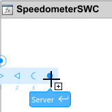
2) In the Property Inspector, on the Parameters tab, locate the newly added port and double-click its name to make it editable. Then, type Curvature and press Enter to rename the port.
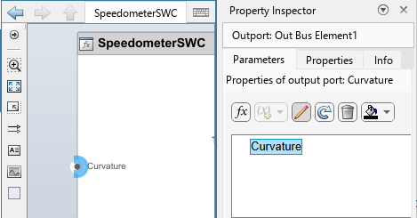
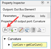
3) Click on the function button  to add a port element to the server port. The element is added with the default name. Click on it to revise it to
 curCurv = getCurCurv().
Add Simulink Function Block
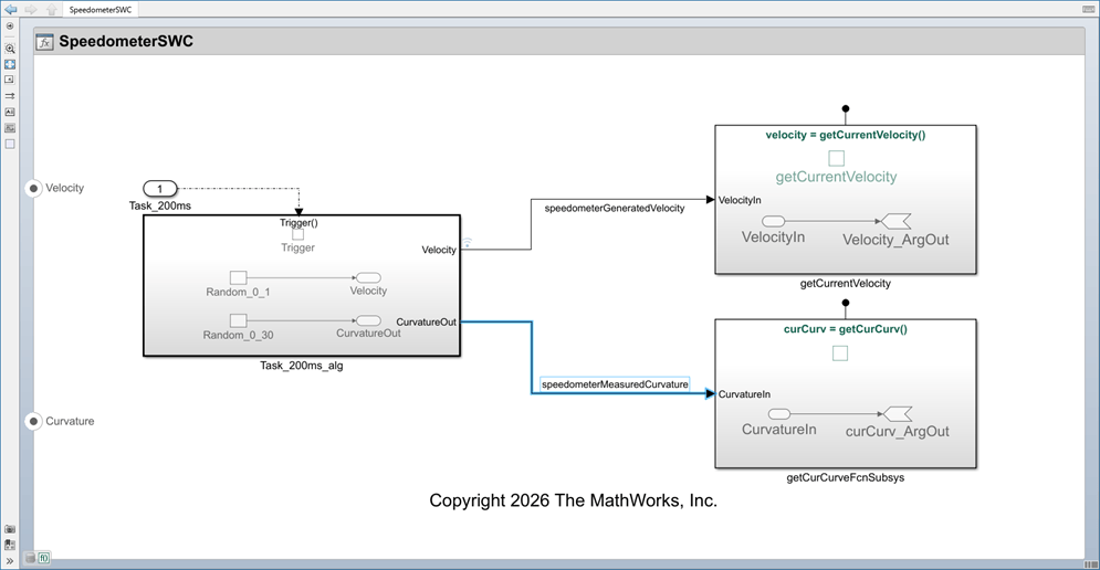
In the speedometer model, add another Simulink Function Subsystem block on top of the existing, and name it getCurCurveFcnSubsys. Then, double-click its prototype and set it to curCurv = getCurCurv(). Double-click the new Simulink function subsystem to open it. Add an Inport block and name it CurvatureIn, then connect the new Inport block to the Arg Out block.
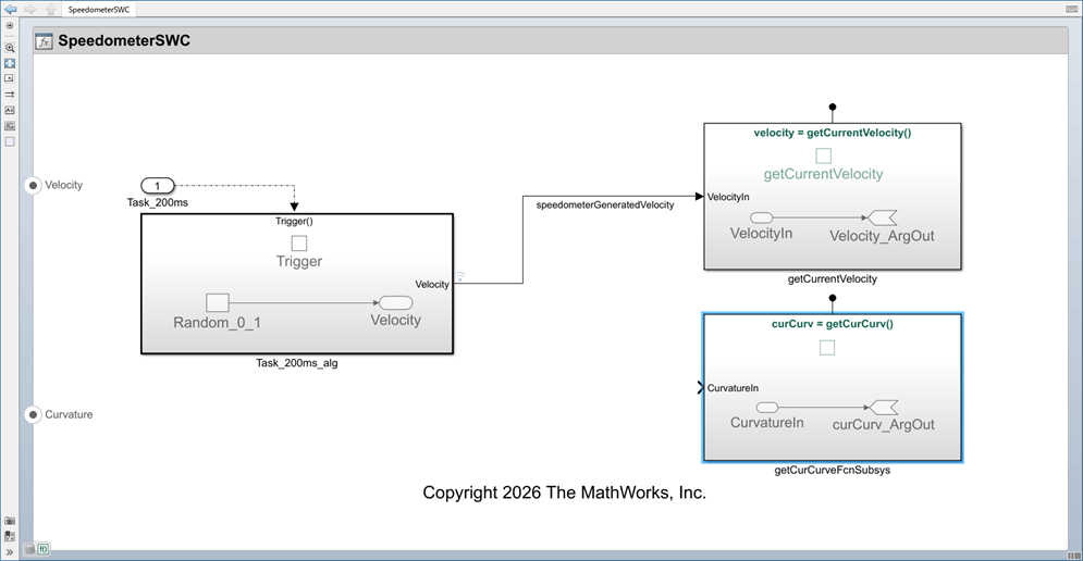
Connect Function-Call Subsystem to New Simulink Function Block
In the function-call subsystem, add a second Random Number block and set its mean value to 0 and its variance value to 30. This number represents the road curvature in degrees. Add a second Outport block in the subsystem and connect it to the Random Number block to this . Name the new outport CurvatureOut. Connect the outport signal of the function-call subsystem to the inport signal of the Simulink function. Name the connecting signal speedometerMeasuredCurvature.
Map Simulink Function to Server Port
Open the Service Mappings editor and select the Servers tab. Locate the new server port entry, getCurCurv, under the parent entry Curvature. In Simulink function column of that entry, click the arrow to open the list, and then select the getCurCurv option to map the new server port element to the Simulink function you added to the model.
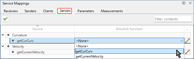
Alternatively, you can configure this property, for single port elements, using the Property Inspector. To learn more, see Configure Communication and Execution Behavior of Software Components.
Update Architecture System
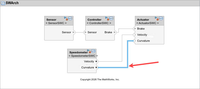
In the parent architecture system, locate the new server port of the SpeedometerSWC model, and the new client port of the ActuactorSWC. In both the port is called Curvature. Connect them to each other.
Generate and Examine Code
Generate code from the models SpeedometerSWC and ActuactorSWC.
Open the code Pane of the model ActuactorSWC and navigate to the generated function ActuatorSWC_OnBrakeCommand in the file ActuatorSWC.cpp. This function is called upon receiving a brake command through the receiver port Brake. In the last part of that function, the functions call_Curvature_getCurCurv and get_result_Curvature_getCurCurv are invoked. Navigate to the file ActuatorSWC_comm.cpp and examine the definition of these functions.
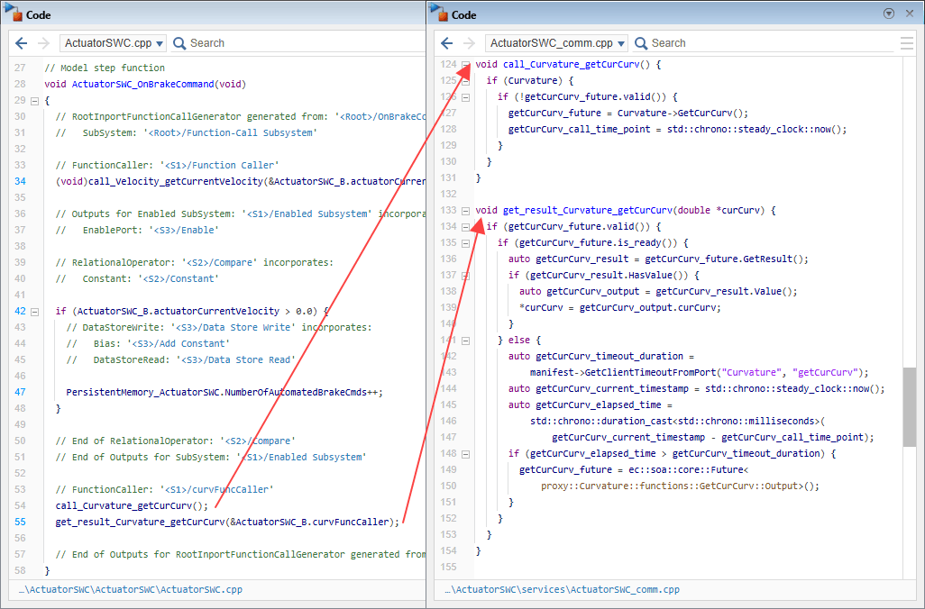
The function caller you added to the model, curvFuncCaller, is calling of these functions. You configured the caller behavior to allow delayed server results, so the first function call initiates the remote invocation of the function getCurCurv, and the second function call is the polling for results. The definitions of these functions belong to the client port. They contain the interactions of the client port with the client services.
Now open the code Pane of the model SpeedometerSWC and navigate to the generated file curvature_skeleton_impl.cpp. In it, examine the function getCurCurv. Now navigate to the file ActuatorSWC_comm.cpp and examine the function SpeedometerSWC_getCurCurv.
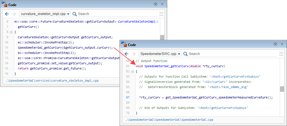
The function getCurCurv in the file curvature_skeleton_impl.cpp is called by the server service, and it invokes the function SpeedometerSWC_getCurCurv in the file ActuatorSWC_comm.cpp, which is the code generated from the Simulink function you added to the model.
See Also
Service Mappings Editor | Servers Service Interface Properties | Clients Service Interface Properties

