Modeling Patterns for AUTOSAR Runnables
Use Simulink® models, subsystems, and functions to model AUTOSAR atomic software components and their runnable entities (runnables).
Multiple Periodic Runnables Configured for Multitasking
Open the example model autosar_swc.slx.
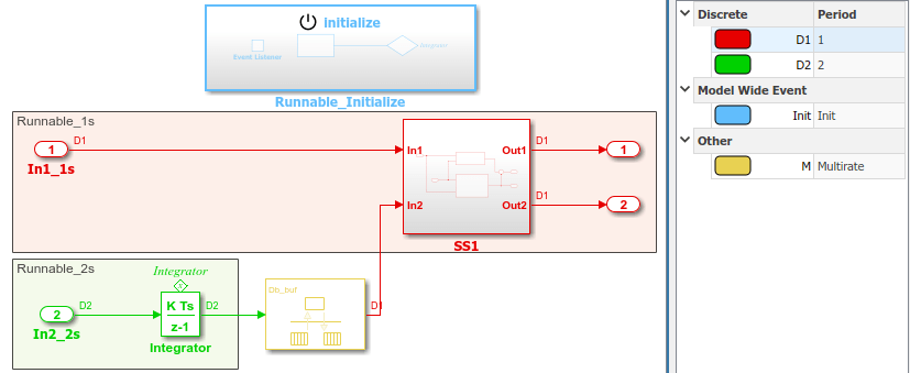
open_system('autosar_swc')The model shows the implementation of an AUTOSAR atomic software component (ASWC). Two periodic runnables, Runnable_1s and Runnable_2s, are modeled with multiple sample rates: 1 second (In1_1s) and 2 seconds (In2_2s). To maximize execution efficiency, the model is configured for multitasking.
The model includes an Initialize Function block, which initializes the integrator in Runnable_2s to a value of 1.
To display color-coded sample rates with annotations and a legend, on the Debug tab, select Diagnostics > Information Overlays > Colors.
Relevant Model Configuration Parameter Settings
Solver > Type set to
Fixed-step.Solver > Solver set to
discrete (no continuous states).Solver > Fixed-step size (fundamental sample time) set to
auto.Solver > Treat each discrete rate as a separate task selected.
Scheduling
In the model window, enable sample time color-coding by selecting the Debug tab and selecting Diagnostics > Information Overlays > Colors. The sample time legend shows the implicit rate grouping. Red represents the fastest discrete rate. Green represents the second fastest discrete rate. Yellow represents the mixture of the two rates.
Because the model has multiple rates and the Solver parameter Treat each discrete rate as a separate task is selected, the model simulates in multitasking mode. The model handles the rate transition for In2_2s explicitly with the Rate Transition block.
The Rate Transition block parameter Ensure deterministic data transfer is cleared to facilitate integration into an AUTOSAR run-time environment.
The generated code for the model schedules subrates in the model. In this example, the rate for Inport block In2_2s, the green rate, is a subrate. The generated code properly transfers data between tasks that run at the different rates.
Generate Code and Report (Embedded Coder)
If you have Simulink Coder and Embedded Coder software, generate code and a code generation report. The example model generates a report.
Generated code complies with AUTOSAR so that you can schedule the code with the AUTOSAR run-time environment.
Review Generated Code
In the code generation report, review the generated code.
autosar_swc.ccontains entry points for the code that implements the model algorithm. This file includes the rate scheduling code.autosar_swc.hdeclares model data structures and a public interface to the model entry points and data structures.autosar_swc_private.hcontains localdefineconstants and local data required by the model and subsystems.autosar_swc_types.hprovides forward declarations for the real-time model data structure and the parameters data structure.rtwtypes.hdefines data types, structures, and macros that the generated code requires.autosar_swc_component.arxml,autosar_swc_datatype.arxml,autosar_swc_implementation.arxml, andautosar_swc_interface.arxmlcontain elements and objects that represent AUTOSAR software components, ports, interfaces, data types, and packages. You integrate ARXML files into an AUTOSAR run-time environment. You can import ARXML files into the Simulink environment by using the AUTOSAR ARXML importer tool.Compiler.h,Platform_Types.h,Rte_ASWC.h,Rte_Type.h, andStd_Types.hcontain stub implementations of AUTOSAR run-time environment functions. Use these files to test the generated code in Simulink, for example, in software-in-the-loop (SIL) or processor-in-the-loop (PIL) simulations of the component under test.
Code Interface
Open and review the Code Interface Report. This information is captured in the ARXML files. The run-time environment generator uses the ARXML descriptions to interface the code into an AUTOSAR run-time environment.
Input ports:
Require port, interface: sender-receiver of type
real-Tof 1 dimensionRequire port, interface: sender-receiver of type
real-Tof 1 dimension
Entry-point functions:
Initialization entry-point function,
void Runnable_Initialize(void). At startup, call this function once.Output and update entry-point function,
void Runnable_1s(void). Call this function periodically at the fastest rate in the model. For this model, call the function every second. To achieve real-time execution, attach this function to a timer.Output and update entry-point function,
void Runnable_2s(void). Call this function periodically at the second fastest rate in the model. For this model, call the function every 2 seconds. To achieve real-time execution, attach this function to a timer.
Output ports:
Provide port, interface: sender-receiver of type
real-Tof 1 dimensionProvide port, interface: sender-receiver of type
real-Tof 1 dimension
Multiple Runnables Configured as Periodic-Rate Runnable and Asynchronous Function-Call Runnable
Open the example model autosar_swc_fcncalls.slx.
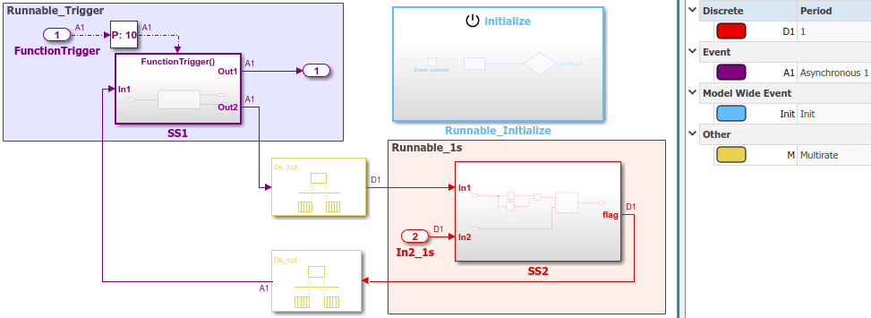
open_system('autosar_swc_fcncalls')The model shows the implementation of an AUTOSAR atomic software component (ASWC). The model uses an asynchronous function-call runnable, Runnable_Trigger, which is triggered by an external event. The model also includes a periodic rate-based runnable, Runnable_1s. The Rate Transition blocks represent inter-runnable variables (IRVs).
Use this approach to model the JMAAB complex control model type beta architecture. In JMAAB type beta modeling, at the top level of a control model, you place function layers above scheduling layers.
The model includes an Initialize Function block, which initializes the unit delay in Runnable_1s to a value of 0.
To display color-coded sample rates with annotations and a legend, on the Debug tab, select Diagnostics > Information Overlays > Colors.
Relevant Model Configuration Parameter Settings
Solver > Type set to
Fixed-step.Solver > Solver set to
discrete (no continuous states).Solver > Fixed-step size (fundamental sample time) set to 1.
Solver > Treat each discrete rate as a separate task cleared.
Scheduling
In the model window, enable sample time color-coding by selecting the Debug tab and selecting Diagnostics > Information Overlays > Colors. The sample time legend shows the implicit rate grouping. Red represents the discrete rate. Magenta represents the asynchronous function trigger. Yellow represents the mixture of two rates.
The asynchronous trigger runnable runs at asynchronous rates (the Sample time type parameter of the function-call subsystem Trigger block is set to |triggered]) while the periodic rate runnable runs at the specified discrete rate. The generated code manages the rates by using single-tasking assumptions. For models with one discrete rate, the code generator does not produce scheduling code because there is only a single rate to execute. Use this technique for a single-rate application when you have one periodic runnable.
The model handles transitions between the asynchronous and discrete rates of the connected runnables with the two Rate Transition blocks. The Rate Transition block parameter Ensure deterministic data transfer is cleared to facilitate integration into an AUTOSAR run-time environment.
Generate Code and Report (Embedded Coder)
If you have Simulink Coder and Embedded Coder software, generate code and a code generation report. The example model generates a report.
Generated code complies with AUTOSAR so that you can schedule the code with the AUTOSAR run-time environment.
Review Generated Code
In the code generation report, review the generated code.
autosar_swc_fcncalls.ccontains entry points for the code that implements the model algorithm. This file includes the rate scheduling code.autosar_swc_fcncalls.hdeclares model data structures and a public interface to the model entry points and data structures.autosar_swc_fcncalls_private.hcontains localdefineconstants and local data required by the model and subsystems.autosar_swc_fcncalls_types.hprovides forward declarations for the real-time model data structure and the parameters data structure.rtwtypes.hdefines data types, structures, and macros that the generated code requires.autosar_swc_fcncalls_component.arxml,autosar_swc_fcncalls_datatype.arxml,autosar_swc_fcncalls_implementation.arxml, andautosar_swc_fcncalls_interface.arxmlcontain elements and objects that represent AUTOSAR software components, ports, interfaces, data types, and packages. You integrate ARXML files into an AUTOSAR run-time environment. You can import ARXML files into the Simulink environment by using the AUTOSAR ARXML importer tool.Compiler.h,Platform_Types.h,Rte_ASWC.h,Rte_Type.h, andStd_Types.hcontain stub implementations of AUTOSAR run-time environment functions. Use these files to test the generated code in Simulink, for example, in software-in-the-loop (SIL) or processor-in-the-loop (PIL) simulations of the component under test.
Code Interface
Open and review the Code Interface Report. This information is captured in the ARXML files. The run-time environment generator uses the ARXML descriptions to interface the code into an AUTOSAR run-time environment.
Input port:
Require port, interface: sender-receiver of type
real-Tof 1 dimension
Entry-point functions:
Initialization entry-point function,
void Runnable_Initialize(void). At startup, call this function once.Simulink function,
void Runnable_1s(void). Call this function periodically at the fastest rate in the model. For this model, call the function every second. To achieve real-time execution, attach this function to a timer.Exported function,
void Runnable_Trigger(void). Call this function at any time from an external trigger.
Output port:
Provide port, interface: sender-receiver of type
real-Tof 1 dimension
Multiple Runnables Configured As Function-Call Subsystem and Simulink Function
Open the example model autosar_swc_slfcns.slx.
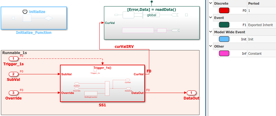
open_system('autosar_swc_slfcns')The model shows the implementation of an AUTOSAR atomic software component (ASWC). The model includes one periodic rate runnable, Runnable_1s, that uses a function-call subsystem, SS1. The model also includes a Simulink function, readData, to provide a value (CurVal) to clients that request it.
The model includes an Initialize Function block, which initializes the unit delay in subsystem RollingCounter to a value of 0.
To display color-coded sample rates with annotations and a legend, on the Debug tab, select Diagnostics > Information Overlays > Colors.
Use function-call subsystems:
When it is difficult or not possible to specify system events in a Simulink model.
To achieve complex multirate scheduling of runnables. Model each rate as a separate function-call subsystem.
Relevant Model Configuration Parameter Settings
Solver > Type set to
Fixed-step.Solver > Solver set to
discrete (no continuous states).Solver > Fixed-step size (fundamental sample time) set to 1.
Solver > Treat each discrete rate as a separate task selected.
Scheduling
In the model window, enable sample time color-coding by selecting the Debug tab and selecting Diagnostics > Information Overlays > Colors. The sample time legend shows the implicit rate grouping. Red identifies the discrete rate. Green identifies rates inherited from exported functions, indicating their execution is outside the context of Simulink scheduling.
Your execution framework must schedule the generated function code and handle data transfers between functions.
Generate Code and Report (Embedded Coder)
If you have Simulink Coder and Embedded Coder software, generate code and a code generation report. The example model generates a report.
The code generator:
Produces an AUTOSAR runnable for the function-call subsystem at the root level of the model.
Implements signal connections between runnables as AUTOSAR inter-runnable variables (IRVs).
Generated code complies with AUTOSAR so that you can schedule the code with the AUTOSAR run-time environment.
Review Generated Code
In the code generation report, review the generated code.
autosar_swc_slfcns.ccontains entry points for the code that implements the model algorithm. This file includes the rate scheduling code.autosar_swc_slfcns.hdeclares model data structures and a public interface to the model entry points and data structures.autosar_swc_slfcns_private.hcontains localdefineconstants and local data required by the model and subsystems.autosar_swc_slfcns_types.hprovides forward declarations for the real-time model data structure and the parameters data structure.readData_private.hcontains localdefineconstants and local data required by the Simulink function.rtwtypes.hdefines data types, structures, and macros that the generated code requires.autosar_swc_slfcns_component.arxml,autosar_swc_slfcns_datatype.arxml,autosar_swc_slfcns_implementation.arxml, andautosar_swc_slfcns_interface.arxmlcontain elements and objects that represent AUTOSAR software components, ports, interfaces, data types, and packages. You integrate ARXML files into an AUTOSAR run-time environment. You can import ARXML files into the Simulink environment by using the AUTOSAR ARXML importer tool.Compiler.h,Platform_Types.h,Rte_ASWC.h,Rte_Type.h, andStd_Types.hcontain stub implementations of AUTOSAR run-time environment functions. Use these files to test the generated code in Simulink, for example, in software-in-the-loop (SIL) or processor-in-the-loop (PIL) simulations of the component under test.
Code Interface
Open and review the Code Interface Report. This information is captured in the ARXML files. The run-time environment generator uses the ARXML descriptions to interface the code into an AUTOSAR run-time environment.
Input ports:
Require port, interface: sender-receiver of type
uint16_Tof 1 dimensionRequire port, interface: sender-receiver of type
real_Tof 1 dimension
Entry-point functions:
Initialization entry-point function,
void Runnable_Init(void). At startup, call this function once.Exported function,
void Runnable_1s(void). Call this function periodically, every second.Simulink function,
Std_ReturnType readData(real_T Data[2]). Call this function at any time.
Output ports:
Provide port, interface: sender-receiver of type
uint16-Tof 1 dimension